


Electronics and sensors ·
Align an ultrasonic sensor on a prototype board with a twin-opening stand
Keep a two-transducer module steady during a tabletop experiment. Match the front openings, PCB hole pattern and rear spacing to the actual sensor.
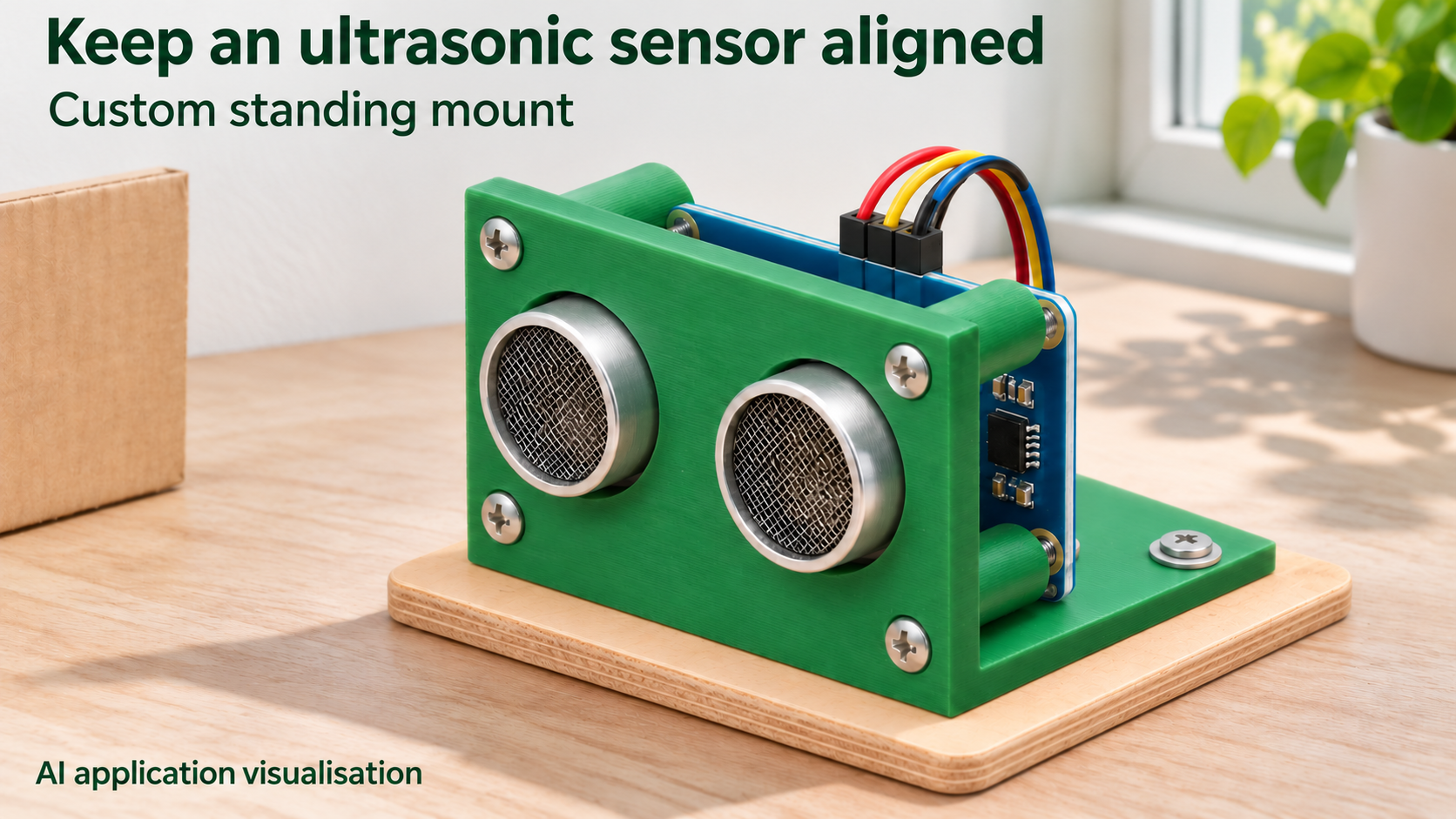
A fixed starting position for tabletop experiments
In a simple distance experiment, the sensor should not tip whenever a cable moves. This stand holds a module with two side-by-side transducers upright. The transducers pass through two front openings; four rear standoffs support a matching PCB. Two foot holes allow fastening to a prototype board.
The sensor, screws, opposing fasteners and electronics are separate items. This is a mechanical mount; it generates neither measurements nor a distance display. The illustrated application is a stationary tabletop setup.
Measure transducers and PCB independently
Measure transducer case diameter and centre spacing. can_d is the finished opening diameter including your chosen clearance; can_pitch is the distance between the two axes. Do not clamp the metal cans or transfer mounting forces into their solder joints.
pcb_x and pcb_z describe horizontal and vertical centre spacing of a rectangular four-hole pattern, not PCB outside dimensions. Measure all four holes and check components on both board faces. An HC-SR04 label alone does not establish fit. A module without a matching four-hole pattern is not automatically suitable.
Rear spacing and overall size
Defaults are can_d 16.5 mm, can_pitch 26 mm, pcb_x 40 mm, pcb_z 20 mm, rear_gap 8 mm, wall 3 mm, pcb_d 2.4 mm and foot_depth 30 mm. rear_gap is the standoff length behind the front plate. The PCB support plane is therefore wall plus rear_gap, 11 mm behind the front face. The transducers must be long enough for their faces not to remain recessed behind the printed plate.
Standoff diameter is pcb_d plus 4 mm, or 6.4 mm. Width is the larger of can_pitch plus can_d plus twice wall, and pcb_x plus standoff diameter plus 2 mm: 48.5 mm by default. Front-plate height is similarly derived from transducer size and vertical hole spacing, giving 28.4 mm. With the 3 mm foot, total height is 31.4 mm.
Adjustment ranges and fixed foot holes
Ranges are transducer opening 10–25 mm, transducer spacing 18–45 mm, horizontal hole spacing 28–65 mm, vertical spacing 10–30 mm, rear gap 4–16 mm, wall 2.4–5 mm, PCB bore 1.8–3.5 mm and foot depth 18–50 mm. can_pitch must exceed can_d plus 2 mm. The model also checks whether standoffs overlap the transducer openings.
Foot depth must exceed wall plus rear_gap plus 3 mm. Both foot holes remain 3.4 mm independently of pcb_d, each 6 mm from the side and rear edges. Screw heads, tools and connectors need additional room; the geometry checks do not cover every real assembly.
Print, assemble and check the experiment
One possible print orientation is front face down. Inspect foot overhang and support needs in the slicer, then deburr openings and screw channels. Fasten the PCB flat against all four standoffs without bending it or bridging traces with metal hardware. Select screw length for the front plate, standoffs, PCB and opposing fasteners. Secure the foot to a flat board and relieve cable strain.
Before testing, check clear transducer faces, fasteners and electrical connections against the specific sensor’s requirements. Test against a fixed target to determine whether the mounting suits your measurements. The holder guarantees neither range nor accuracy. It is not for vehicle guidance or protective shutdowns. The image is an AI application visualisation; no physical print or measurement test is documented.
Next step