


Mechanisms and model making ·
Configure a square-bore gear for a hand-operated mechanism trial
Match tooth geometry, face width and shaft opening to your own test assembly. A square bore can engage directly with the matching shaft shape.
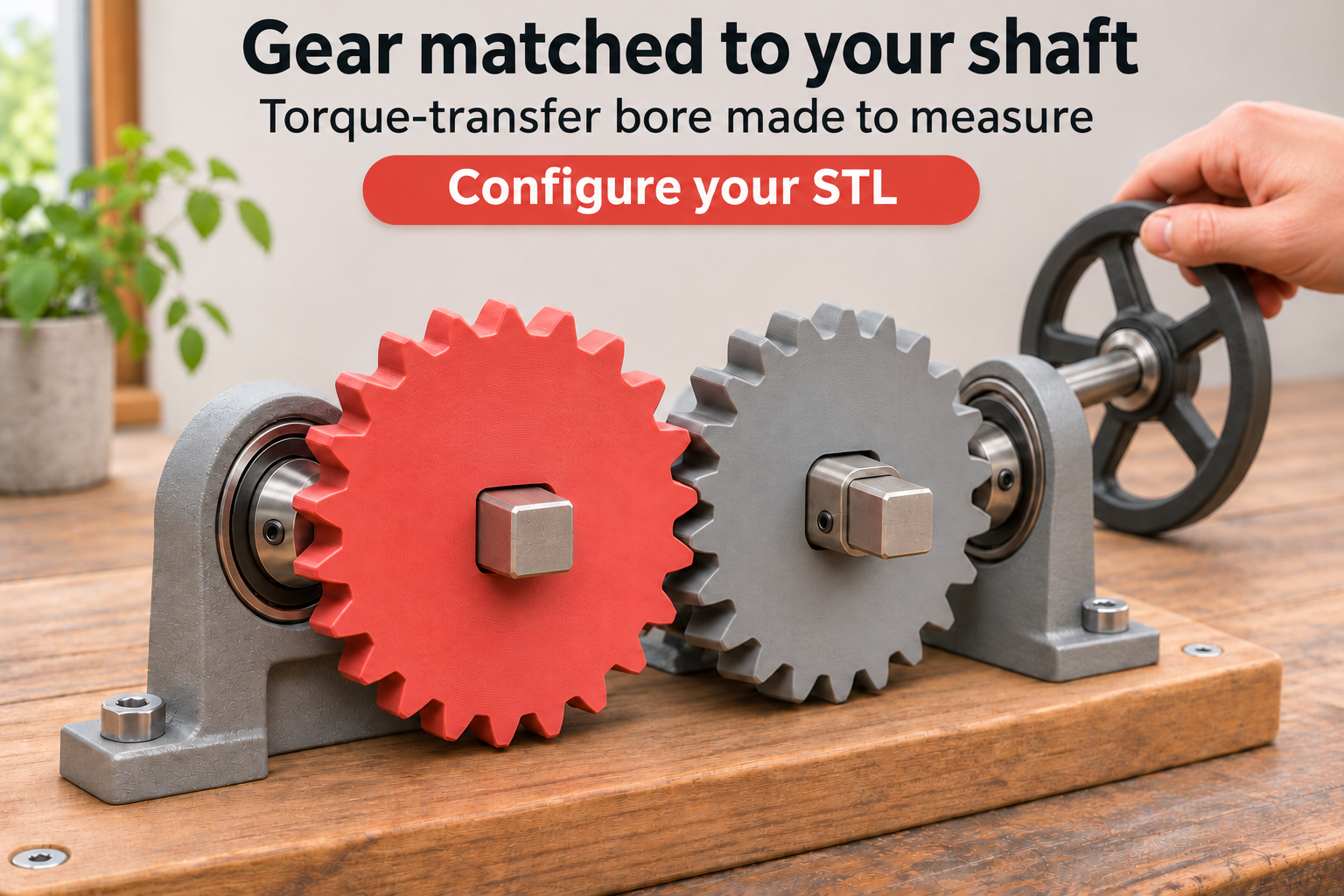
Plan the gear around the shaft connection
In a small manually driven mechanism, a gear needs a suitable connection to its shaft. This parametric spur gear can be made with a square opening through its centre. The application shows a matching square shaft; bearings, mating gear and handwheel belong to the separate demonstration assembly.
Measure the shaft across opposite flats and allow for the fit produced by your printer. The bore does not automatically prevent axial movement, so provide suitable separate stops. A round bore is also available, but on its own it does not provide the same shape-based torque connection as a fitted square.
Coordinate teeth, bore and available material
Tooth count accepts integers from 8 to 100 and module ranges from 0.2 to 10, starting at 20 teeth and module 2. Face width ranges from 1 to 200 mm, initially 12 mm. The construction uses an involute profile with a 20-degree pressure angle. Select the mating gear, shaft spacing and surrounding clearance to suit the chosen tooth geometry.
For the square option, bore size means the side length of the square, initially 8 mm. The construction limits non-round openings to 63 mm, but that does not make every large bore suitable for every small gear. Inspect the remaining wall towards the tooth roots. Optional shoulders can be added on either or both sides; selecting none leaves a flat gear body.
Check orientation and the actual printed fit
Tooth orientation can place a tooth centre or a gap centre on the +X reference while the bore stays fixed. The difference is 180 degrees divided by tooth count. This is useful when the tooth pattern needs a defined position relative to the square shaft. The legacy setting preserves the previous orientation. Optional edge chamfer is limited internally to one quarter of face width or half the module, whichever is smaller.
Choose material and print setup for your trial and check bore fit on a sample first. Remove burrs without changing the tooth contour. Turn the assembled pair slowly by hand and inspect binding, play and alignment. Parameter ranges do not establish tested torque, speed or service life. Shafts, bearings, axial stops and the mating gear are separate components.
The image is an AI application visualization, not a photograph of a physically tested print. Accessories shown are not included in the STL.
Next step