


Hobby covers ·
Retain a light hobby cover with a printed quarter-turn button
Insert a crossbar through a cover and retaining bridge, then turn it 90 degrees. Plan the slot, clearance and installation space for your light removable cover.
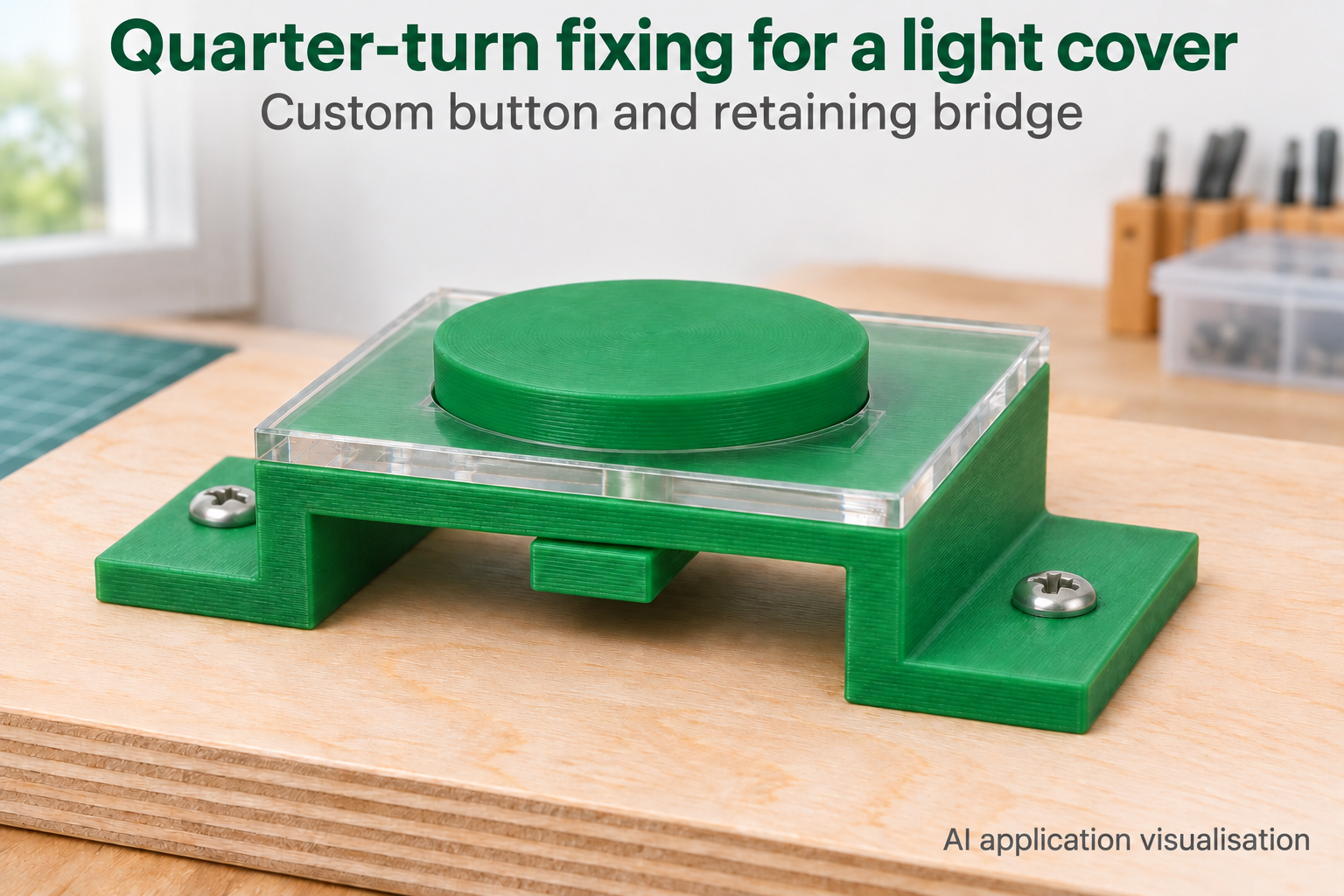
Retain a removable cover with a quarter turn
A thin cover on a dry hobby project may need occasional removal. This two-piece fixing combines a screw-mounted bridge with a separate button, shaft and crossbar. Insert the bar through the aligned slots in the cover and bridge. Turn it a quarter turn so that it lies across the slot beneath the bridge and prevents straightforward withdrawal.
To open, turn the bar back into alignment and lift the button out. The button becomes a loose part. There is no detent, spring or adjustable preload. Check its rotational position on your own assembly; the model does not provide a guaranteed self-locking action.
Give the cover a matching elongated opening
Cover thickness adjusts from 1 to 6 mm, with a 3 mm default. Crossbar length adjusts from 14 to 30 mm and width from 4.5 to 9 mm. The bridge slot is rectangular: bar length plus total allowance by bar width plus total allowance. The cover needs a matching clear opening directly above it.
For a 20 mm bar, 6 mm width and 0.5 mm allowance, the slot measures 20.5 × 6.5 mm. The round button disc is then 26 mm in diameter and 3 mm thick. The disc stays above the cover while the crossbar goes below the bridge. The image shows the turned retaining position, not an arrangement of loose components.
Reserve the space below the bridge
Shaft diameter adjusts from 3.5 to 6 mm and bridge thickness from 2.4 to 5 mm. The distance between the button disc and crossbar includes cover thickness, bridge thickness and total allowance. A thicker cover substituted later can prevent insertion or rotation.
The 5–14 mm foot height creates space beneath the bridge; crossbar thickness is fixed at 3 mm. Check its complete swept area, including clearance to screw heads and adjacent components. Total allowance adjusts from 0.3 to 0.9 mm. It is neither spring travel nor a rated clamping stroke.
Check the printed fit before mounting
Outer fixing holes adjust from 2.5 to 5 mm. Select suitable screws for the support and keep both feet seated flat. Depending on print orientation, the bridge and button may need supports. Remove support residue from the slot, shaft and bar without unnecessarily reducing the retaining surfaces.
Try the sequence without force: insert through both slots, turn beneath the bridge, then release again. If it binds, check the dimensions and printed surfaces. A larger cover may need additional supports or fixing points chosen for the particular project. A single button does not imply a rated load capacity.
Use limits and the next step
Use this model only for light, dry hobby covers. It has no safety, sealing or vibration-locking function and no specified retention force. The image is an AI application visualisation. No physical test prints have been made.
After checking the dimensions and fit on your project, configure the model and print the STL yourself or select the manufacturing option available on the model page.
Next step