


Light model drives ·
Align a small flange motor and pulley with a slotted mounting bracket
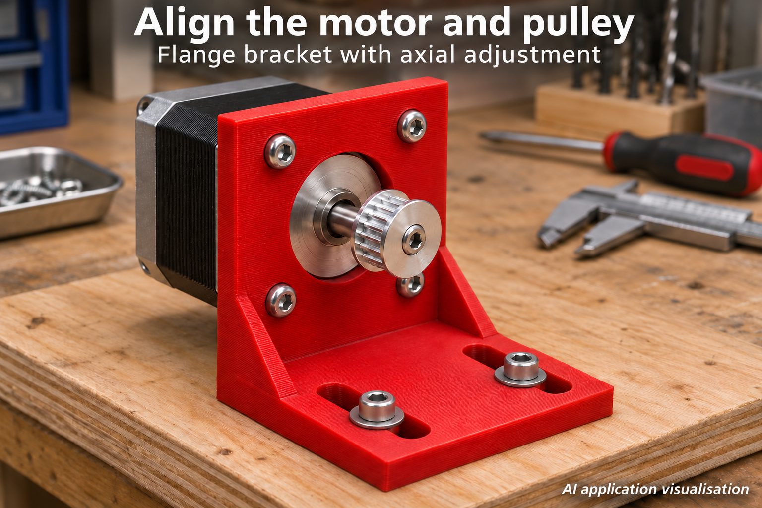
Four face screws secure the motor while two base slots allow movement along its shaft. Match the bracket to your hole pattern, locating boss and shaft height.
Bring the motor pulley into the correct plane
A light tabletop model needs its motor pulley aligned with the mating pulley. This bracket holds the motor using four face screws. The motor body sits behind the upright plate, while the shaft passes through the central opening and projects over the foot. Two side ribs brace the upright.
The base slots run parallel to the motor shaft. Loosening the base screws therefore allows axial movement of the whole motor, useful for aligning the pulley plane. In a conventional belt drive with parallel shafts, this direction does not alter shaft centre distance and is not the usual belt-tension adjustment. Your assembly needs another adjustment method for that.
Measure the four-hole pattern and locating boss
Square mounting pitch adjusts from 20 to 50 mm. Measure centre-to-centre spacing in both directions and check that the actual motor pattern is square. Face width adjusts from 35 to 70 mm and must leave adequate fastening margins. Motor screw clearance adjusts from 2.5 to 5 mm.
The 12–38 mm central opening must clear the locating boss. Measure its required diameter and include suitable fit clearance. The configurator limits overlap between this opening and the screw holes. Defaults of 31 mm pitch and a 22.5 mm opening do not guarantee universal NEMA compatibility.
Plan shaft height, base depth and travel
Shaft height above the underside of the foot adjusts from 24 to 55 mm; base depth adjusts from 38 to 75 mm. Reserve space behind the plate for the motor and ahead for the pulley and mating drive. Material thickness adjusts from 3 to 6 mm. Side-rib depth is fixed at 12 mm.
The 6–28 mm travel parameter defines the distance between the slot’s rounded-end centres. Slot width is fixed at 4.4 mm and total slot length is travel plus 4.4 mm. Actual screw movement also depends on shank diameter and surrounding parts. A short foot cannot accommodate every large travel setting.
Assemble and align with the drive stopped
Print on the foot and inspect the horizontal motor holes for residue. Select motor screws for the actual thread and permitted engagement depth. Include plate thickness and any washers when choosing length. The locating boss must not prevent the motor face from sitting flat.
Attach the foot with two suitable screws and washers. With the drive switched off, loosen them slightly, slide the bracket along its slots, check pulley alignment and retighten evenly. Washers must reliably span the slots. Then check that the shaft and pulley move freely and the bracket has not distorted.
A light model mount without continuous-load validation
This bracket is intended for small tabletop models with low belt tension. Motor temperature, stiffness and creep behaviour of the printed material must suit the application. No continuous-load approval or rated belt force is provided. Geometric fit alone does not establish suitability for every operating load.
The image is an AI application visualisation of the mounted alignment stage before fitting the belt. No physical test prints have been made. After checking your dimensions, configure the STL or use the manufacturing option available on the model page.
Next step