


Photography & optics ·
Replace missing binocular eyepiece caps with a custom TPU double cover
Cover both eyepieces when putting your binoculars away. Measure the rims, socket spacing and insertion depth before configuring a printable TPU replacement.
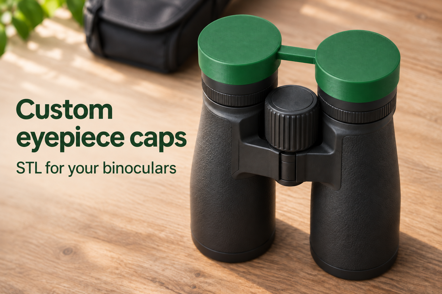
Cover both eyepieces between outings
Your binoculars still work, but their shared eyepiece cover has gone missing. A replacement needs to match the outside of the eyepiece rims, so the objective-lens diameter alone will not tell you which cap to choose. This configurable design uses two closed TPU cups connected at their bases by one flat bridge. They fit over the two small, eye-facing eyepieces together.
The intended use is storage between observations. This part is neither an optical filter nor a watertight seal. Remove the complete cover before looking through the binoculars. The larger objective lenses at the opposite end are not the surfaces covered in this application.
Measure the rims and distinguish gap from centre distance
Measure the outer rim of each eyepiece where the cap will sit, rather than the exposed glass. Both sockets use the same inner diameter, so check that the two rims have matching dimensions and suit a circular push-on cover. You can set the inner diameter from 30 to 60 mm. TPU flexibility and printer tolerances affect the finished fit; test the fit before relying on the replacement.
Adjust the binocular hinge to the position you intend to use for storage. The socket-gap setting means the clear space between the two circular openings, not the distance between their centres. For example, a 40 mm inner diameter plus a 20 mm gap gives a 60 mm centre distance. If you measure centre to centre, subtract the chosen inner diameter to obtain the gap setting. The available gap range is 8 to 30 mm.
Choose a depth that leaves the glass untouched
Clear insertion depth can be set from 5 to 16 mm; the default is 10 mm. The eyepiece rim must locate the cap while keeping its closed base clear of the optical surface. Include the storage position of adjustable eyecups in your measurements. A deeper cover is not necessarily a better fit if it reaches a housing shoulder or touches the glass.
The design has fixed 1.6 mm walls and bases. Its connecting bridge is 8 mm wide and 1.6 mm thick. These are not separate settings: the three configurable dimensions control socket diameter, gap and clear insertion depth.
Print the cups upright and check a gentle fit
The model recommends TPU 95A, 0.2 mm layers and at least four perimeters as a starting point. Print with the closed bases on the bed and the openings facing upward. Remove strings and inspect the inner surfaces before fitting the cover. It should go on and come off gently, without forcing either eyepiece. Do not use the bridge as a carrying handle or force the binocular hinge to a different spacing while the caps are fitted.
The image is an AI application visualization, not a photograph of a physically tested print; binoculars are not included. Configure the double eyepiece cover to your measurements and purchase the STL for home printing.
Next step