


Display grids and indoor organizers ·
Fasten a lightweight wire display grid to a board with a two-part cross clamp
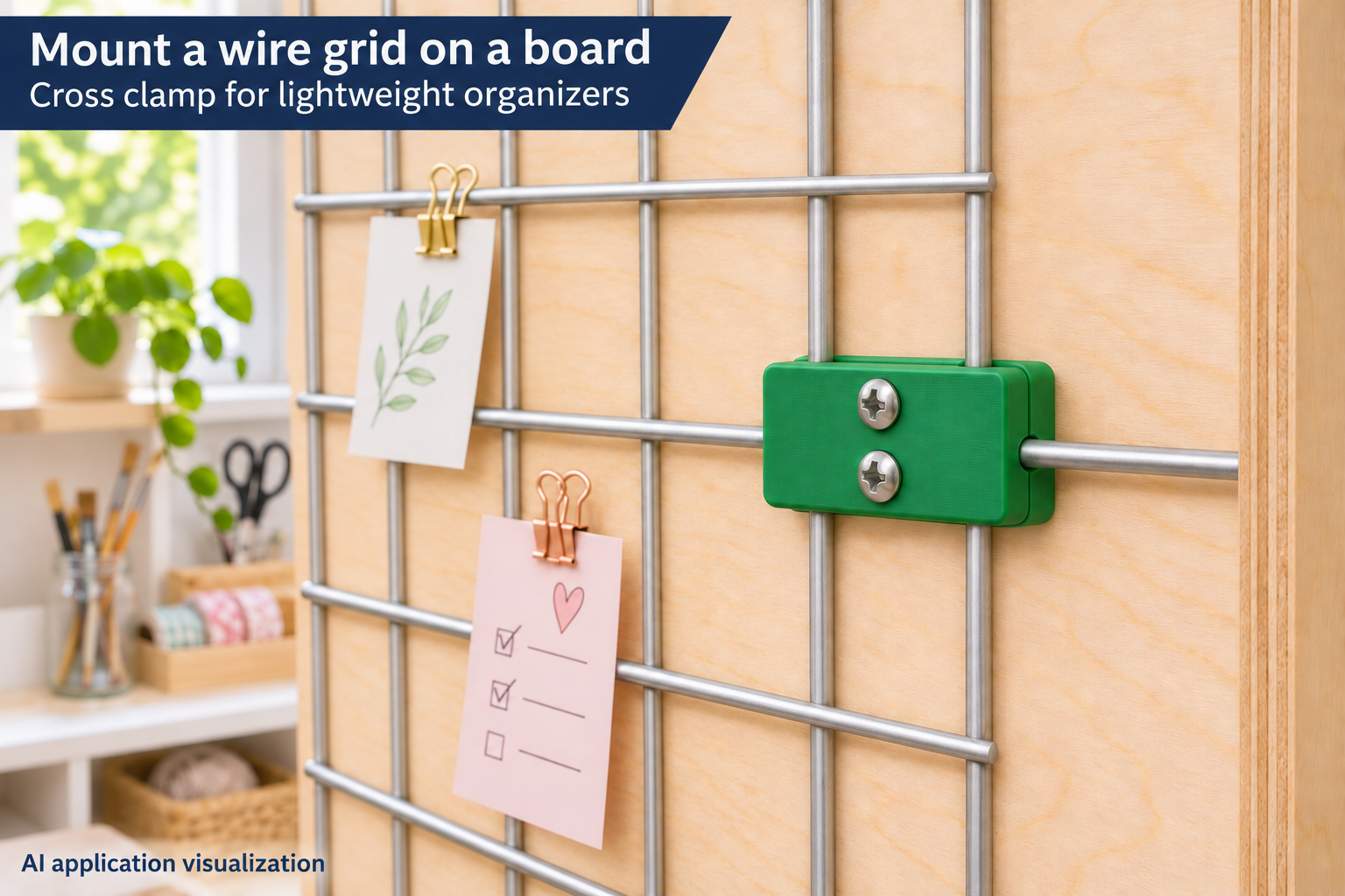
Two printed halves capture parallel grid wires and the crosswire above them. Matching the actual wire diameters and centre offset gives an indoor organizer a suitable mounting point.
Use a wire crossing as a locating point
A lightweight grid for paper notes needs a board attachment that does not simply slide along its wires. This clamp captures two parallel longitudinal wires and one crosswire lying above them. The captured crosswire limits sideways movement of the grid.
The lower saddle rests against your supporting surface. The cap fits over it with its open channels facing inwards. Two screws outside the crosswire channel pass through both halves into the support. Supply the grid, screws and suitable backing separately.
Measure the two wire layers separately
Longitudinal and crosswire diameters each adjust from 2.5 to 6 mm, initially 4 mm. Measure the actual thickness including any coating. The centre spacing of the parallel wires is 15–55 mm, with 30 mm as the default.
Height offset is the distance between wire centres perpendicular to the grid plane, not the size of a neighbouring mesh opening. It adjusts from 2.5 to 8 mm, initially 4 mm. Measure the actual welded grid; the crosswire sits on the outer side of the longitudinal wires. Check any different arrangement before using this geometry.
Allow clearance and room for the screws
Total fit allowance is 0.2–0.8 mm, initially 0.4 mm. It is added once to each wire diameter, not once on each side. Wire pitch remains a centre-to-centre dimension. Try the fit on your own print before tightening the screws.
Wall thickness is 2.4–5 mm and screw passage 2.5–5 mm, initially 3 and 3.4 mm. Wire pitch must exceed longitudinal-wire diameter plus screw passage plus twice the wall thickness. Height offset must be at least the average of both wire diameters minus 0.4 mm. These constraints reject unsuitable parameter combinations but do not replace a real fit check.
Turn the cap over for assembly
Both parts are arranged for printing with their open recesses facing upwards. Flip the cap for installation. Seat the parallel wires in the lower saddle and align the crosswire with the cap channel. The screws pass beside the crossing rather than through any wire.
Choose screws and mounting locations to suit your backing board. Tighten evenly only until the parts seat correctly; do not deform the plastic by overtightening. Intended for lightweight indoor display grids and organizers, not fencing, fall protection or cable support structures. The image is an AI application visualization; no physical test prints have been performed.
Next step