


Electronics and workbench ·
Stand a small fan upright: a mounting frame for the workbench
Mount a square low-voltage fan on a prototype board. Match the frame, hole pattern and air opening, then secure its two feet to the base.
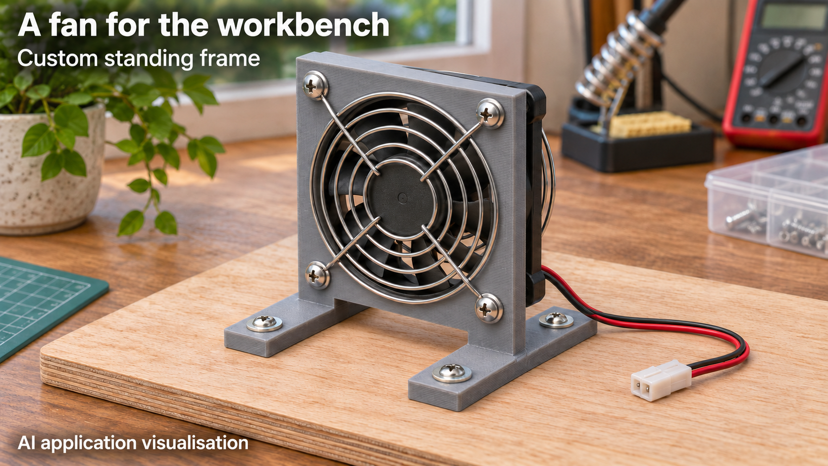
Attach an existing fan to a board
A small square fan usually has mounting holes but no feet for standing on a workbench. This one-piece frame holds it upright. Four corner bores connect the fan to the vertical plate, while the circular centre remains open for airflow. Two feet extend both forwards and backwards and can be screwed to a prototype board.
The illustrated use is assembly of a small low-voltage fan before connection. The fan, guards, fasteners and suitable power supply are separate items. The printed frame itself does not prevent contact with the blades.
Measure the hole pattern and opening together
Measure the fan housing and centre-to-centre distance between adjacent mounting holes. pitch is the horizontal and vertical spacing of a square pattern, not its diagonal. There are no adjustment slots: shifting the fan cannot compensate for an incorrect pitch.
The round air_d opening must suit the fan’s free opening while leaving material around the screw holes. The 48 mm default may cover part of some fans’ openings. Frame width and model name do not establish a guaranteed fan size. Compare the actual outlines before printing.
Seven settings and fixed foot holes
Defaults are frame_w 64 mm, pitch 50 mm, air_d 48 mm, lift 8 mm, foot_depth 52 mm, wall 4 mm and bolt_d 4.4 mm. Overall height is lift plus frame_w, or 72 mm. The airflow axis sits at lift plus half the frame width, or 40 mm.
Ranges are frame 42–120 mm, pitch 32–105 mm, opening 25–102 mm, lift 4–20 mm, foot depth 30–85 mm, wall 3–6 mm and fan bore 3–5.5 mm. Each foot is three times wall wide, 12 mm by default. Its two vertical holes stay at 3.4 mm diameter, each 6 mm from the foot end; bolt_d does not change them.
The model requires frame_w to be at least pitch plus bolt_d plus 6 mm. air_d must be smaller than frame_w minus 8 mm. Also, air_d/2 plus bolt_d/2 plus 2 mm must remain below pitch divided by the square root of 2. Individual range limits therefore cannot all be combined.
Print and fasten the complete assembly
One possible print orientation places the frame front on the bed; projecting feet may then need supports. Inspect contact and overhangs in the slicer. Deburr the bores without damaging the narrow material beside the air opening. Choose four suitable fasteners long enough for the frame, fan, guards and opposing fastening hardware.
Fit suitable guards to accessible sides and check blade clearance. Secure the feet to a flat base. Washers distribute screw pressure; avoid distorting the plastic. Route cables away from the rotor and provide strain relief. Before connecting a suitable low-voltage supply, check free rotation, polarity, fasteners and stability.
What performance the frame does not establish
The holder specifies no airflow, cooling capacity, noise reduction or vibration rating. A larger opening alone does not guarantee better operation. Material, print orientation and fan weight affect stiffness, so the actual assembly needs its own checks.
The image is an AI application visualisation of an unpowered assembly with separate guards. It does not document a physical print or operational test. Extraction and filtration are not functions of this model.
Next step