


Workspace & storage ·
Store a closed laptop under a table with custom slide-in rails
Two separate rails create storage for a switched-off notebook. Match the opening height, support ledges and installed spacing to your own device.
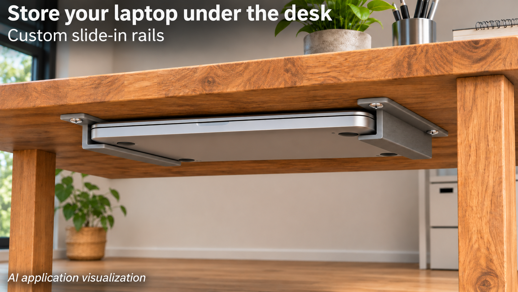
A storage place for a switched-off notebook
A closed notebook can occupy useful desk space after work. A storage position under a side section of the table may help. These two rails support the device along its lower side edges while leaving the centre open. Short rear stops limit how far it slides in.
This application is for stationary storage of a switched-off, cooled-down device. It does not establish suitability for docked operation or adequate cooling while charging. Choose a location outside the knee area and not above people. The image is an AI application visualization, not evidence of a physical load test.
Check the case and support areas first
Measure the maximum thickness of the closed device, including feet and protrusions. Add suitable sliding clearance and the thickness of any protective pads. clear_h controls the distance from the top of the lower ledge to the underside of the upper flange; its default is 22 mm.
Inspect the actual areas of the underside that will rest on the rails. Rounded or strongly tapered edges should not balance on a narrow line. Keep ports, vents and hinges clear. Thin protective pads are separate accessories: they reduce the available height and change the effective height of the rear stops.
Space the two rails around the device
The gap between rails is not an STL parameter. Install the mirrored parts parallel, setting their internal spacing around the notebook with some sideways clearance. Bottom ledges point inward and upper screw flanges point outward. The notebook should slide without wedging and have adequate support on both sides.
Defaults are rail_l = 120 mm, ledge = 24 mm and wall = 4 mm. Each rail is 30 mm high overall and 40.4 mm wide including its outer flange. Match rail length to the device depth: the support must safely carry its centre of gravity even if the front projects beyond the rails. No load capacity is guaranteed.
Plan four screws and the rear stops
Each rail has two vertical through-holes in its outer flange. At mount_d = 4.4 mm and pitch = 80 mm, their centres are 20 and 100 mm from the open end. The holes are not countersunk. Select suitable screws and, if needed, washers for the actual tabletop.
Check the board material, thickness, strength and required screw engagement. Screw tips must not emerge through the top surface. Hollow-core furniture requires appropriate fixings. Avoid crushing the printed flanges by overtightening.
The default rear stop is 6 mm high and occupies the last 4 mm of the 120 mm rail. The usable distance to its front face is therefore 116 mm. Check that it actually catches the case. There is no front latch: the notebook remains removable and can slide out if the assembly is tilted or moved.
Print and trial-fit the assembly
The STL contains both rails as separate pieces. Orient each on its outer sidewall for printing and inspect the layer preview. Deburr support edges and check bores, flanges and stops.
Try a suitable lightweight template first, then hold the device supported while checking fit. Confirm even contact and adequate support length before releasing it. Do not use the assembly for mobile storage; remove the notebook before moving the table. Adjust all seven parameters and the physical installation to your device.
Next step