


Optics and passive tabletop experiments ·
Hold a triangular glass prism near one end with a printed clamp
A separate screw bridge retains the prism over a flat printed base. Thin soft liners and a correctly sized triangular opening leave most of its long faces exposed.
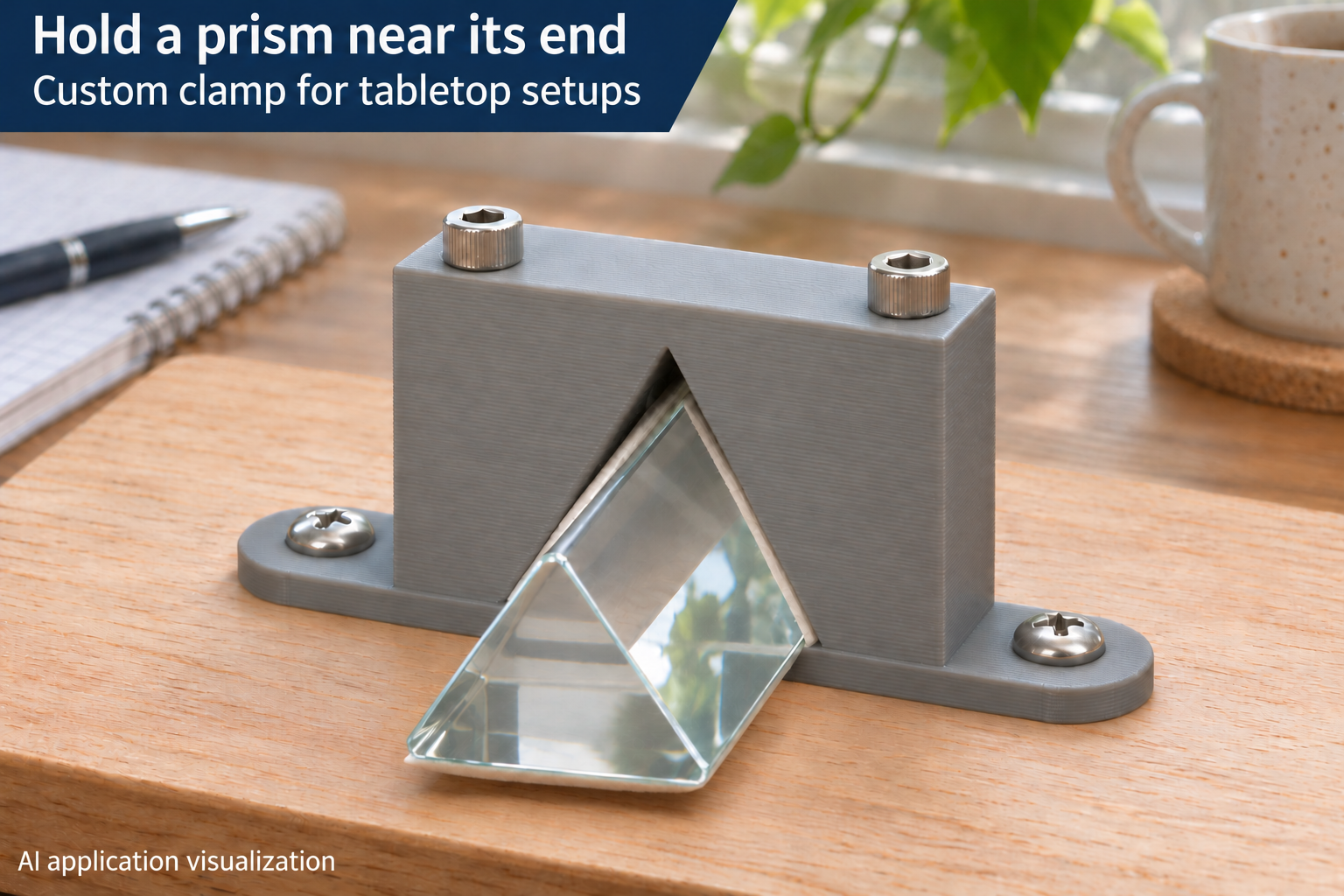
Keep the long prism faces accessible
A small passive tabletop demonstration needs a glass prism held steady while most of its long faces remain exposed. This end clamp grips only a short section. The prism rests with a flat base face down on a printed support, while a separate bridge surrounds its two sloping sides.
The opening is designed for an isosceles triangular cross-section. Two screws with separate nuts connect bridge and base. Two additional holes in the outer base ends fasten it to an experiment board. This geometry is not intended for round rods or arbitrary asymmetric prisms.
Measure the actual glass width and height
Base width adjusts from 15 to 45 mm and height from 10 to 40 mm, starting at 25 and 21.7 mm. Measure both on your actual prism rather than assuming a standard angle. Its bottom face must sit horizontally in the holder.
Fit allowance is 0.2–1.2 mm, initially 0.6 mm. The model adds it once to the configured width and once to the height. It does not add that much padding at every contact face. Account for thin soft liners and printing tolerance together, then check the combination without applying clamping force.
Choose the end grip and screw layout
Grip length ranges from 6 to 20 mm and starts at 10 mm. Choose a short section suitable for a small prism; a long heavy overhang is outside this intended tabletop application. Wall thickness is adjustable from 2 to 5 mm and also sets the base thickness.
All four screw holes share a diameter of 2.4–5.4 mm, initially 3.4 mm. The outer mounting-hole spacing is 35–80 mm, starting at 50 mm. As prism width or wall thickness increases, leave enough spacing for those holes to remain outside the bridge. The holes are plain through holes, without printed threads.
Add soft liners and close the bridge gently
Fasten the base onto a flat support. Provide clearance for the two bridge-screw nuts, for example with suitable through holes in the wooden board and nuts underneath. The base must not rock on protruding nuts. Match screw length and head bearing surfaces to the complete assembly.
Place thin soft liners between glass and plastic, then lower the bridge squarely. Tighten both screws only gently and evenly, without stressing the glass. Check seating on your own trial print. This is for passive demonstrations with harmless visible light, not lasers or specified optical precision. Glass, liners and screws are separate items. The picture is an AI application visualization; no physical test prints have been performed.
Next step