


Workshop & organisation ·
Keep a pegboard hook from lifting out with a custom TPU retaining bridge
When a hook comes away with a lightweight brush, a fitted retaining bridge can hold its wire shank against the pegboard.
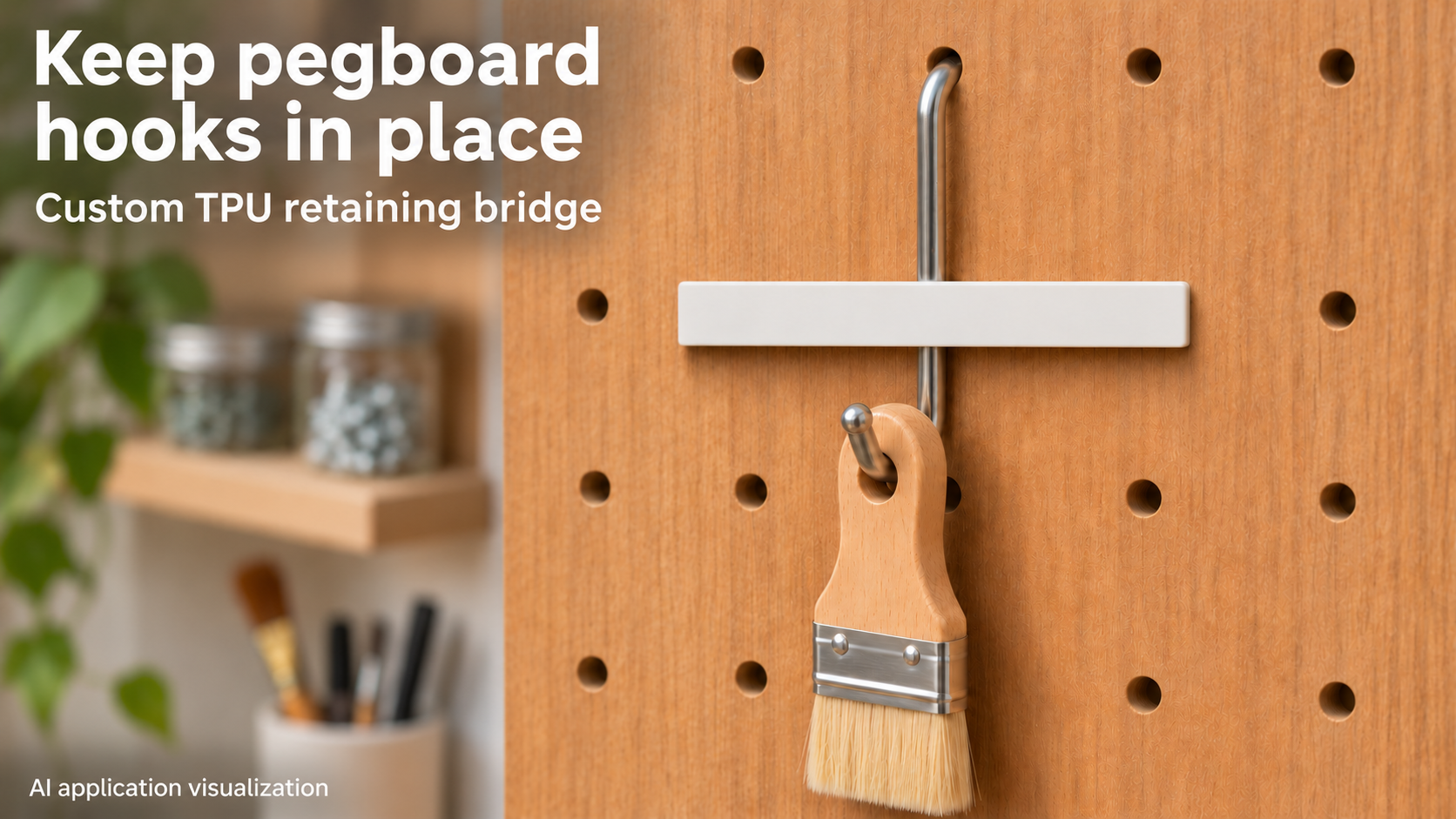
When the hook comes off with the item
A lightweight brush hangs neatly on a pegboard, but lifting it can also lift the hook out of its hole. This retaining bridge is intended to reduce that unwanted movement. It spans the wire of an already fitted hook, with two integral pins entering free holes to its left and right.
The existing metal hook still carries the item. The bridge is not a replacement hook and does not establish a higher load rating. The image illustrates a possible light-brush application; it is an AI visualization, not a photograph of a physically tested print.
Measure the two holes you will actually use
Measure the centre-to-centre distance between the free holes on either side of the wire. pitch means that complete distance, not necessarily one pegboard grid interval. For example, selecting holes with one intervening hole on a 25 mm grid can give a spacing of 50 mm.
Also measure hole_d, board thickness board_t and wire diameter wire_d. Check the hook shape: a flat section of its shank must fit behind the bridge without the pins colliding with other fittings or a rear mounting batten. Universal compatibility with square holes or other hook shapes is not claimed.
Understand the seven adjustments
The default bridge is 58 mm long, 10 mm wide and 2.4 mm thick. With hole_d = 6 mm and fit = 0.3 mm, its straight pin sections are 5.7 mm in diameter. That is 0.3 mm total diametral clearance, not clearance on each side.
wire_d = 4 mm and fit = 0.3 mm provide a nominal 4.3 mm space between the bridge’s inner face and the front of the board when the retaining shoulders meet the rear surface. This does not automatically clamp the wire without play. strap_w and strap_t change bridge width and thickness; flexibility also depends strongly on the TPU and print.
Check the pins and space behind the board
The rear enlargements start after the specified board section. Their largest diameter is hole_d + 0.5 mm, or 6.5 mm here; they are 1.4 mm long and taper towards the tip. A fixed 1 mm slot splits the board-engaging section and tip so they can yield during insertion. Leave space behind the board for the enlargements and their deformation.
Fit the metal hook first. Place the bridge across its shank, then gently insert both pins into the selected holes. Check that both ends engage and the wire really is behind the strip. If insertion requires excessive force or damages the hole edges, change the fit instead of driving the pins in with a tool.
Print in TPU and test gently
The model is intended for flexible TPU. Print the flat bridge on the bed with both pins pointing up. Inspect the slots and retaining enlargements in the slicer; remove strings without cutting into the pins. No particular Shore hardness or retaining force has been validated.
Try insertion and removal without an item first, then with a lightweight accessory. Look for cracks and permanent distortion. This bridge is not a rated safety retainer for heavy tools or items hanging over people. Set all seven values around your own pegboard and existing hook.
Next step