


Lighting & workspace ·
Aim a tabletop LED profile with a custom tilting saddle
Direct a short aluminium LED profile towards your work area using an end-slide saddle and a separate screw-mounted pivot base.
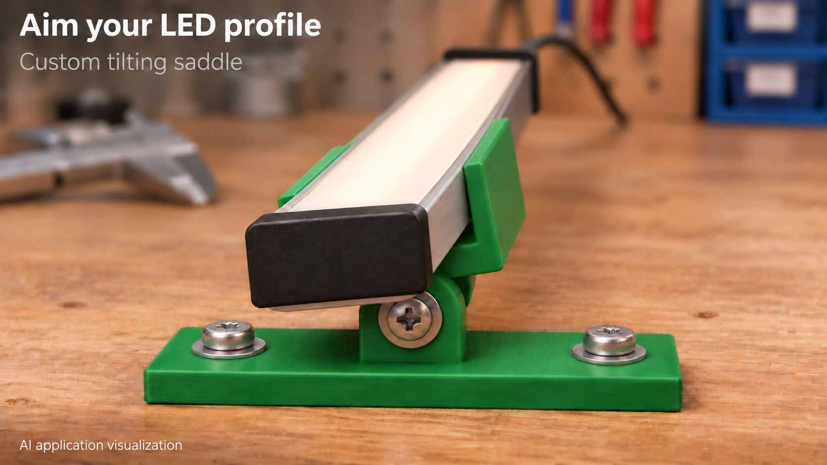
Direct light sideways across the work area
A fixed LED channel can point in the wrong direction on a small desktop setup. This mount allows sideways adjustment after assembly. Its pivot axis runs parallel to the length of the inserted profile, so it changes the direction across the profile rather than providing a ball joint.
The STL contains two separate pieces: a base with one upward tab and a saddle with one downward tab. These tabs sit alongside each other when assembled. Supply your own bolt, washers and nut to join them and clamp the chosen angle.
Measure the complete profile cross-section
Measure the outside width and height of the aluminium profile, including any projecting edges. Check whether the diffuser fits below the guide lips or remains clear between them. The profile slides in from an end; it does not snap in from above. You may need to remove an endcap before insertion.
At the defaults profile_w = 18 mm, profile_h = 8 mm and fit = 0.4 mm, the internal channel is 18.4 mm wide and 8.4 mm high. Clearance is total, not per side. Each upper lip extends inward by a fixed 1.2 mm, leaving a 16 mm central opening. A centred 18 mm profile therefore has a calculated 1 mm overlap on each side.
Size the base and pivot hardware together
The default base measures 42 × 13.4 × 3 mm, with its mounting holes 28 mm apart. pivot_d sets both the pivot bore and base holes, initially 3.4 mm. The saddle is 20 mm long with 3 mm walls and an outside width of 24.4 mm.
Select bolt length, washers and nut around the actual tabs and mounting surface. At a wall thickness of 3 mm, the two tabs together are 6 mm thick, before washers and nut. Tighten only enough to retain the position without visibly distorting the plastic. No particular angular range is guaranteed: check for contact between saddle, base, hardware and profile.
Add separate longitudinal restraint
Both ends of the channel are open, and it has no built-in lengthwise clamp. Provide separate protection against sliding out. The image shows enlarged, independently secured endcaps outside the saddle. They can prevent complete withdrawal only if they cannot pass through the channel and remain firmly attached to the profile. They do not automatically remove all lengthwise movement.
Use suitable additional stops if the profile must stay in one exact position. The LED profile, endcaps, electrical components and fasteners are not included in the printed part. Route the cable so adjustment does not pull or pinch it.
Check the print and your assembled light
Place the tab sides of the separate parts flat for print preparation and inspect the layer preview, especially bores and retaining lips. Deburr contact surfaces and first test insertion with the power disconnected.
This application is for small, cool-running tabletop lights. The part is not electrical insulation and is not intended for hot profiles or overhead mounting. Check fit, clamping, stability and temperature on your own assembly. The image is an AI application visualization; no physical test prints or verified load rating are claimed.
Next step