


Optics and experiments ·
Center a round lens in a printed holder with three adjustment screws
A small round optic rests on an internal ledge while three screws adjust its edge position. Lens diameter, edge thickness and screw height must work together.
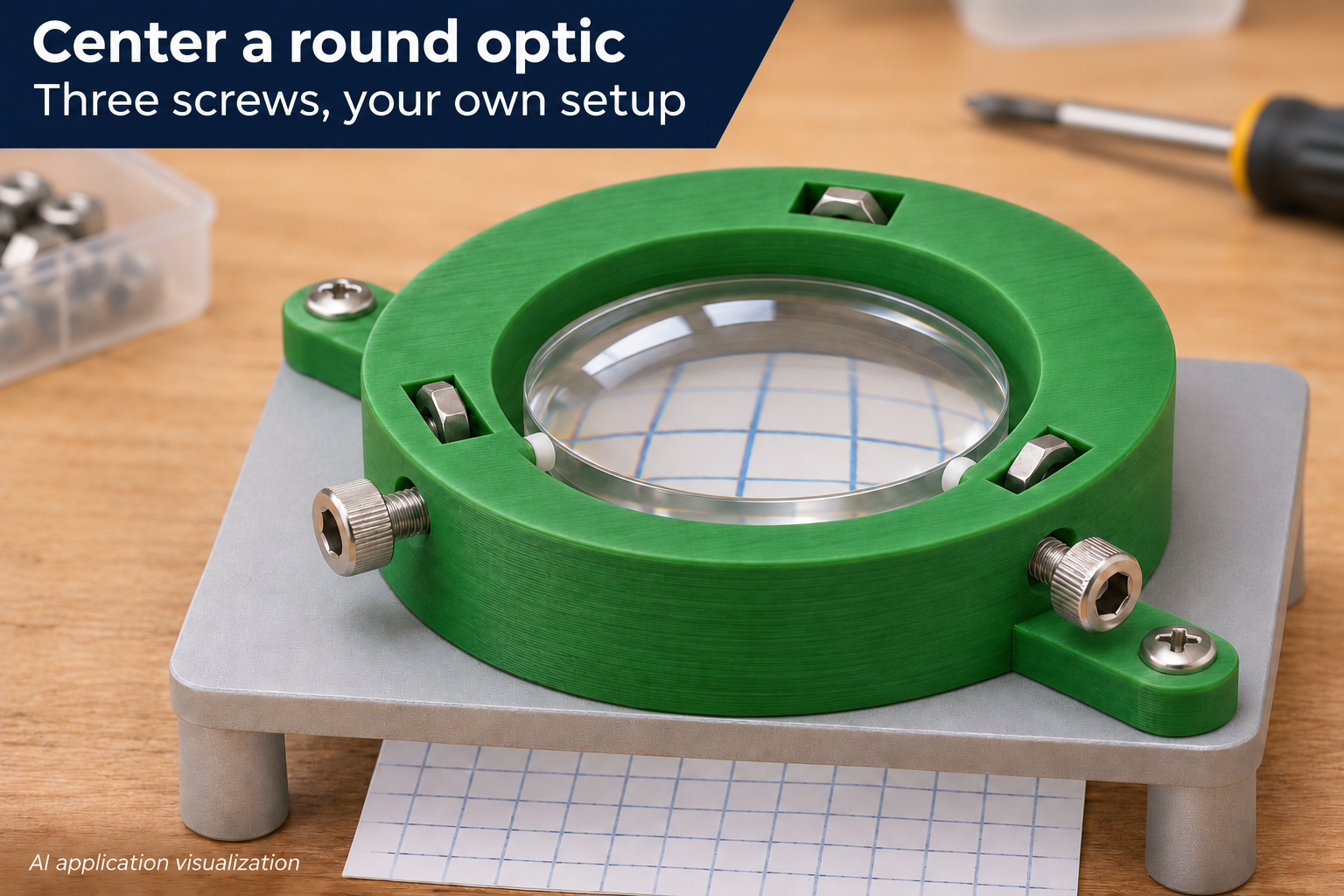
Support a lens in your own tabletop setup
A simple magnifier or optics demonstration needs a round lens positioned above an opening. This annular holder has a narrow support ledge at the bottom. Three radial screws meet the outside edge of the lens, while separate metal nuts fit into rectangular pockets loaded from above.
Each screw is adjusted independently; the holder is not a linked self-centering mechanism. Two opposite low mounting ears attach it to your own support. The lens, screws, nuts and stand are separate from the printed model.
Match the lens to the opening and ledge
The bore is adjustable from 20 to 70 mm, initially 40 mm. The bottom ledge projects 2 mm inward around the circumference and is 1.5 mm high. A 40 mm bore therefore leaves a 36 mm clear opening beneath the optic. The lens needs enough overlap on the ledge while retaining some sideways adjustment clearance.
A lens diameter slightly smaller than the bore, for example by 0.5–2 mm, can be a starting point. Check the actual edge and remaining support area. Longer screws cannot compensate for a lens so small that it no longer rests securely on the ledge.
Make sure the screws touch the cylindrical edge
Ring height ranges from 10 to 22 mm, and the radial screw axes sit halfway up that height. Measure the cylindrical lens edge above its resting surface as well as the lens diameter. The screw tips must meet that edge without pressing on an optical face. A thin lens may be unsuitable even when its diameter fits.
Radial holes can be 3.2–5.5 mm in diameter. Nut width and thickness are adjustable too. Select matching screws with soft contact tips, then check that they run freely through the seated nuts. These pockets hold separate nuts; they are not printed screw threads.
Adjust gently and check the seating
Deburr the print, inspect the flat support ledge and secure the cell to a stand without distorting it. Place the optic inside and advance the three screws in small increments until they lightly meet its edge. Excessive clamping can damage glass. This application concerns passive tabletop experiments; it does not establish optical precision, load capacity or a physically tested assembly.
The image is an AI application visualization, not a photograph of a physically tested print. Illustrated accessories are not included in the STL.
Next step