


Model making and light enclosures ·
Join three panels of a lightweight craft box with a printed inside corner
Three perpendicular faces sit against the floor and two adjoining walls. Two screw passages in each face distribute the attachment across all three panels.
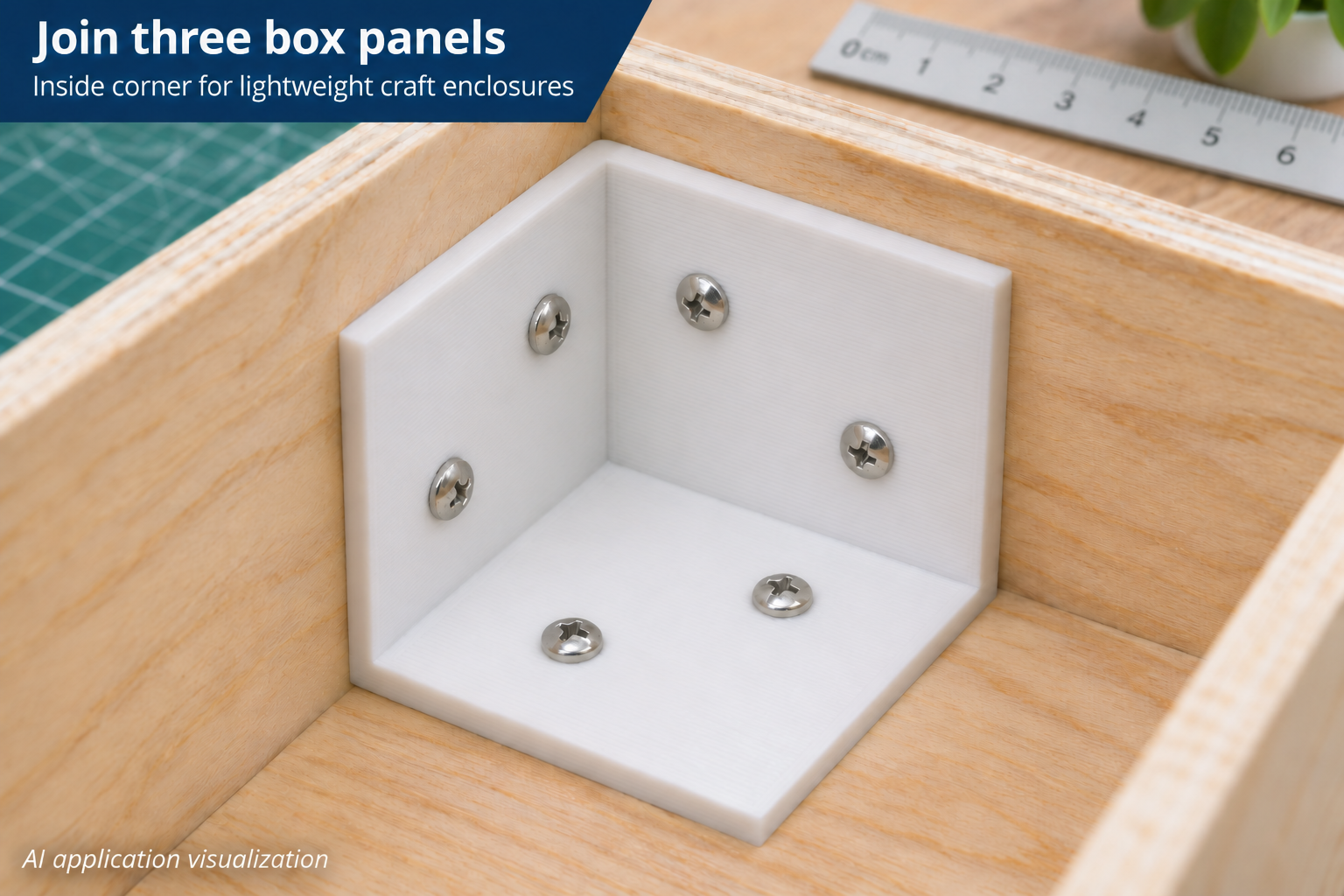
Connect the floor and two side panels together
Three panels meet at the corner of a lightweight model or craft enclosure. This printed connector sits inside, with one face against the floor and two against adjacent walls. All three faces meet at right angles.
Two passages per face provide six fastening points. Screw heads sit on the inward-facing surfaces and the screws pass through the connector into the corresponding backing material. The design is not a tube-profile fitting or an external corner cap.
Size all three legs to the available space
X, Y and Z lengths adjust independently from 25 to 70 mm. Defaults are 40, 35 and 32 mm. These dimensions describe the connector, not the outside size of the box or an automatically allowed panel thickness.
Check that the corner offers enough flat contact area. Cables, installed parts and protruding joints must not sit between the printed part and the enclosure panels. Angles are fixed; tightening screws will not turn an out-of-square box corner into a properly fitted joint.
Account for face thickness and the hole pattern
Each face thickness adjusts separately from 2.4 to 5 mm, initially 3 mm. In the illustrated installation, XY is the floor face and XZ/YZ meet the walls. The shared screw passage is 2.5–5 mm, initially 3.4 mm.
The two holes in each face form a diagonal pair at combined 35/65 and 65/35 percent positions along its dimensions. Their positions change when the legs change. At 35 percent of the shortest leg, there must be clearance for the thickest face plus half the hole diameter and another 1 mm. Invalid parameter combinations are rejected.
Check screw length and screwdriver access
Print on the largest flat face and inspect holes running across the printing direction. Dry-fit the part first: all three outer faces should seat correctly and your screwdriver must reach all six locations. The hole-clearance rule alone does not establish room for every screw head or tool.
Choose screws appropriate for the backing material and short enough to avoid unwanted points emerging outside. Tighten evenly without deforming the plastic or thin panels. Use only for lightweight model and craft enclosures, not load-bearing furniture brackets, transport hardware or safety-critical enclosure reinforcement. The image is an AI application visualization; no physical test prints have been performed.
Next step