


Workshop and marking ·
Repeat measurements from an edge with a fitted steel-ruler stop
Match the slot to your ruler’s width and thickness. A flat end face provides the reference edge, while a separate nut and screw hold the setting.
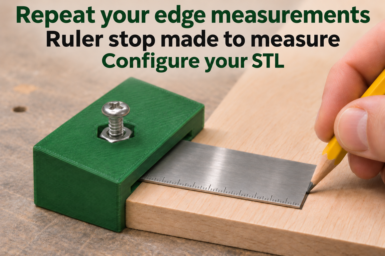
Reuse one setting for several marks
When several marks need the same distance from a workpiece edge, a stop on an existing steel ruler can simplify repeated placement. The ruler passes through a rectangular slot. A flat end face of the printed block contacts the workpiece edge while the ruler extends over its surface.
A separate metal hex nut sits in the upper pocket, and a matching screw presses down onto the ruler. There is no printed thread. During a gentle trial assembly, check that the nut remains seated and the ruler does not slip under light marking pressure. The screw may mark the ruler surface.
Measure the ruler and hardware together
Clear slot width ranges from 12 to 50 mm and thickness from 0.6 to 3 mm. Defaults are 25.4 and 1.2 mm; both must include the required print clearance. Measure the ruler at several points. Body length along the ruler is 18–40 mm, initially 24 mm.
Side margins of 4–12 mm, height below the ruler of 5–18 mm and roof thickness of 6–12 mm define the body; defaults are 7, 9 and 7 mm. Screw clearance is 3.4–5.5 mm, nut width across flats 6.2–9.2 mm and pocket depth 2.4–5 mm. Initial settings are 4.4, 7.2 and 3.4 mm. Check these against your actual hardware.
Check print orientation and the reference face
The roof must be at least 3 mm thicker than the nut pocket depth. Nut width across flats must be at least screw diameter plus 2 mm. Nut width plus 8 mm must be less than body length, and nut width plus 4 mm must be less than slot width.
Rotate the part onto an end face in the slicer so the ruler passage stands vertically. Start with PETG and five walls, and remove elephant foot from reference faces. Fit a suitable short screw and nut, tighten gently and compare the selected reference face against a known measurement. Use the stop for positioning and marking, not as a machine guide or a verified precision gauge.
The image is an AI application visualization, not a photograph of a physically tested print. Accessories shown are not included in the STL.
Next step