


Workspace and cables ·
Fix a USB extension socket to the workspace with a split mounting block
Keep a cable socket within reach on a mounting surface. Two printed halves retain a suitable insulated housing by its front and rear shoulders.
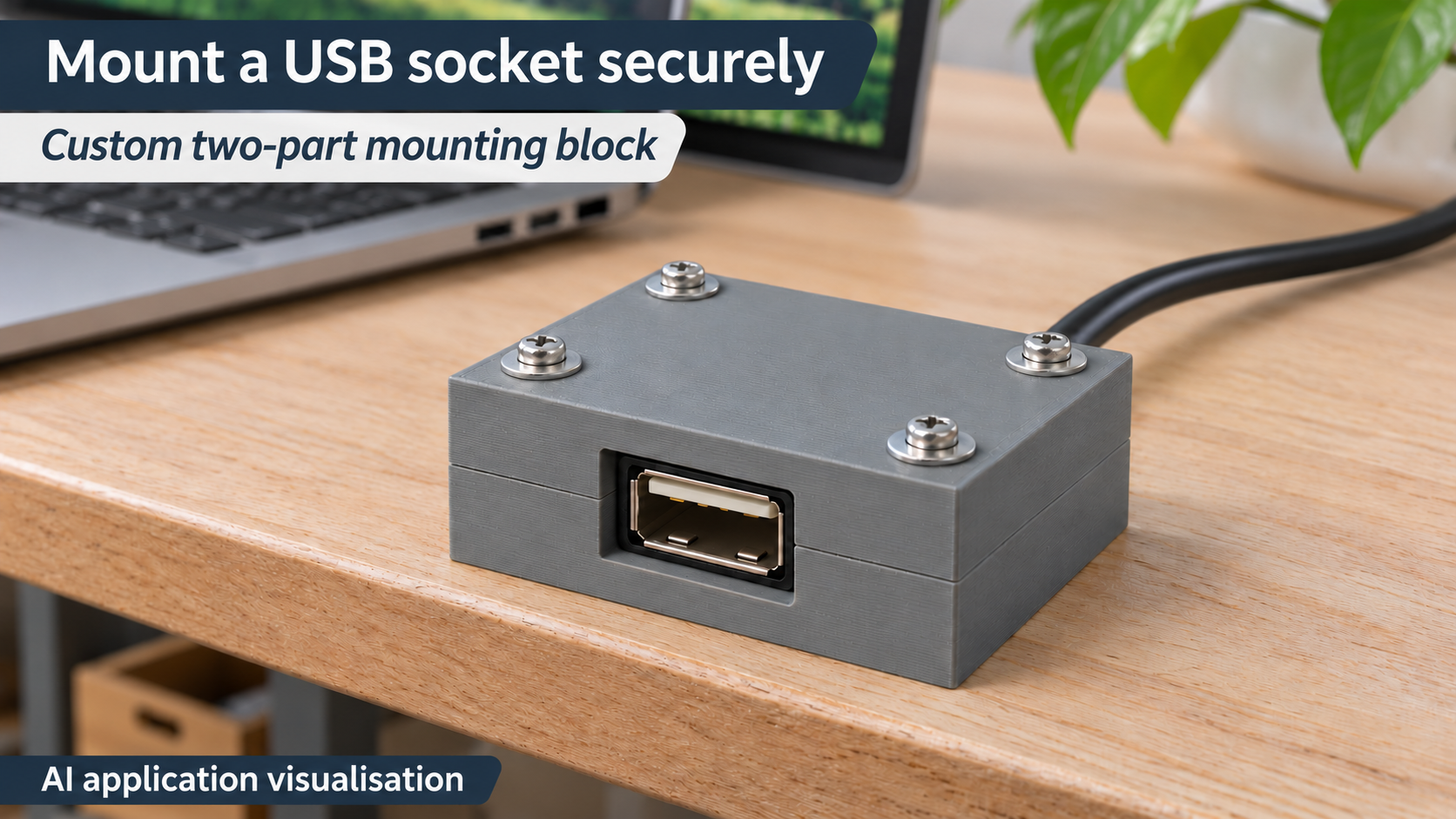
Give a cable socket a fixed position
A USB extension socket can slide across the desk during insertion if it hangs only from its cable. This two-part block receives the rectangular, fully insulated moulded housing of a suitable socket. The smaller front opening and round rear cable outlet limit movement along the mating direction. Four screws join the halves and can also attach the block to your own base.
The print is a mechanical holder. Cable, socket, screws and base are separate items. It changes neither USB version nor charging power or data rate. The illustration uses an existing USB-A extension; other housing shapes need their own fit checks.
A usable housing shoulder is essential
Measure moulded housing width, height and length, plus cable diameter. The housing needs a usable front shoulder and must fit the rectangular pocket. A strongly tapered, rounded or angled housing cannot be reliably described using only its largest outside dimensions.
face_w and face_h define the opening ahead of the socket. It must expose the connection and allow the actual mating plug to enter fully. Check the plug’s grip housing and insertion depth: matching the metal connector face is insufficient if the plastic grip hits the printed edge. This model adds a front wall thickness to consider.
Understand how fit clearance is applied
Defaults are body_w 18 mm, body_h 10 mm, body_l 24 mm, face_w 14 mm, face_h 7 mm, cable_d 5 mm, bolt_d 3.4 mm and fit 0.4 mm. fit is added once to each complete pocket dimension, the front opening width and height, and the cable diameter. It is not 0.4 mm per side.
The resulting pocket is 18.4 × 10.4 × 24.4 mm, front opening 14.4 × 7.4 mm and cable outlet 5.4 mm. With an exactly 18 × 10 mm centred housing, nominal front overlap is 1.8 mm at each side and 1.3 mm above and below. Real clearance, corner radii and position can change that overlap.
Ranges and outside dimensions
Ranges are housing width 12–30 mm, height 8–18 mm, length 16–40 mm, face width 8–24 mm, face height 4–14 mm, cable diameter 3–8 mm, screw clearance 2.5–5 mm and fit 0.2–0.8 mm. Before adding clearance, face_w and face_h must each be at least 2 mm smaller than the corresponding housing dimension. cable_d cannot exceed body_h minus 2 mm.
Wall thickness is bolt_d/2 plus 1.8 mm, or 3.5 mm by default. The closed assembly measures 46.2 mm wide, 31.4 mm deep and 17.4 mm high. Increasing screw clearance therefore changes the overall block too. All four holes are through holes, with no printed threads or nut traps.
Close both halves and test the mating plug
The STL contains two identical halves with open pockets facing up. Print flat, deburr and place the socket in one half. Turn the second half over around the longitudinal axis so the pockets face each other and front and cable openings align. Do not trap the cable at the seam.
Tighten four suitable screws evenly and attach the assembly to a flat mounting surface. Choose length and opposing fastening to suit the base and block height. Mating forces should act on the housing rather than pulling the cable. With power disconnected, test the intended plug for full insertion and check that the socket remains fixed. The block is not certified strain relief. The image is an AI application visualisation; no physical print or insertion-cycle test is documented.
Next step