


Speakers and DIY audio ·
Attach a lightweight speaker grille with printed snap studs and sockets
A mushroom stud on the grille frame clips into a slotted socket on the cabinet. Both printed parts have glue pads and adjustable dimensions for your own assembly.
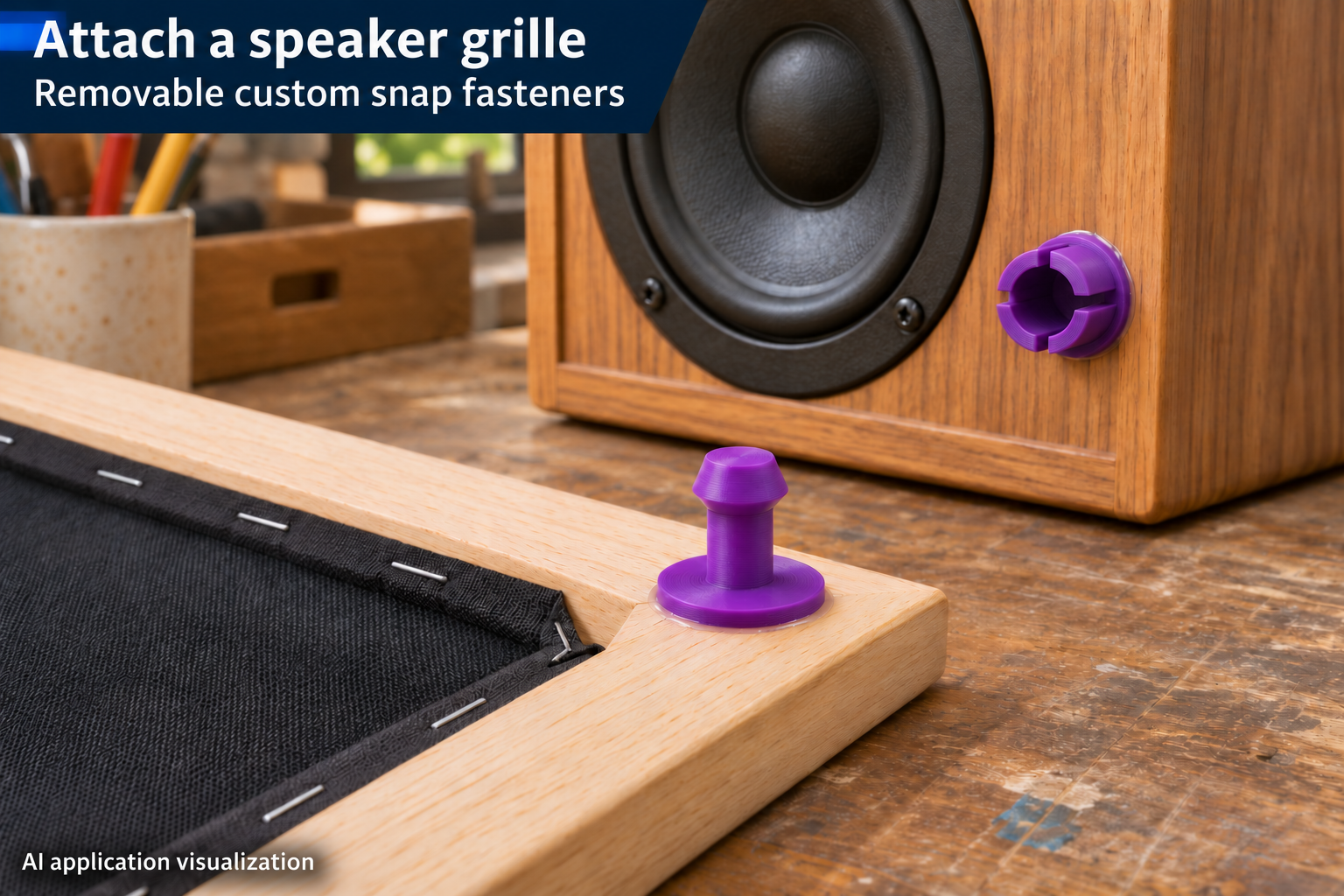
Make a fabric grille that can be removed
A light wooden frame covered with acoustic cloth needs to stay on a DIY speaker while remaining removable. This model provides a stud-and-socket pair for that connection. The enlarged head passes through the narrower socket mouth. Four longitudinal slits divide the upper socket wall into flexible segments.
Bond the stud to the back of the grille frame and the socket to the opposing cabinet front. Each part has a round glue pad without screw holes. The picture shows the detached grille lying back-side up and the matching socket already positioned on the baffle. They are not engaged in this assembly scene.
Match head, neck and retaining overlap
Head diameter adjusts from 5 to 11 mm and neck diameter from 3 to 8 mm, starting at 7 and 4.5 mm. Retaining overlap is 0.15–0.6 mm per side. The mouth diameter equals the head diameter minus twice that overlap: the initial 7 mm head and 0.35 mm overlap produce a 6.3 mm opening.
The internal cavity is designed 0.4 mm larger in diameter than the head. That is a diameter difference, not a guaranteed printed clearance. Neck, mouth and head must work together; the individual maximum settings cannot be combined arbitrarily. Increasing overlap does not automatically improve the connection.
Allow room for the pads and assembled spacing
The round pads can be 12–24 mm across, initially 16 mm, with a fixed 2.4 mm thickness. Find a flat bare area on the frame so folded cloth or staples cannot lift the pad. Place the cabinet socket outside the speaker driver and its surround.
Insertion depth ranges from 7 to 18 mm, socket wall thickness from 1 to 2.2 mm and slit width from 0.6 to 1.5 mm. Check the real frame-to-cabinet spacing with a printed pair engaged. The insertion-depth setting alone is not the finished gap between the two wooden surfaces.
Test one pair before bonding several around the frame
The model calls for tough PETG. First check insertion force, looseness and repeated removal with one printed pair. Then distribute suitable pairs around the lightweight frame and align their axes during a dry fit. The number needed depends on your frame; no load or insertion-cycle rating is provided.
Choose an adhesive compatible with both the printed plastic and the actual wood finish. Follow its preparation and curing instructions, keeping the socket opening and slots free of glue. These fasteners retain the light grille frame; they do not support the speaker cabinet. The image is an AI application visualization, and no physical test prints have been performed.
Next step