


Prototype input controls ·
Mount a single keyboard switch on your own prototype base
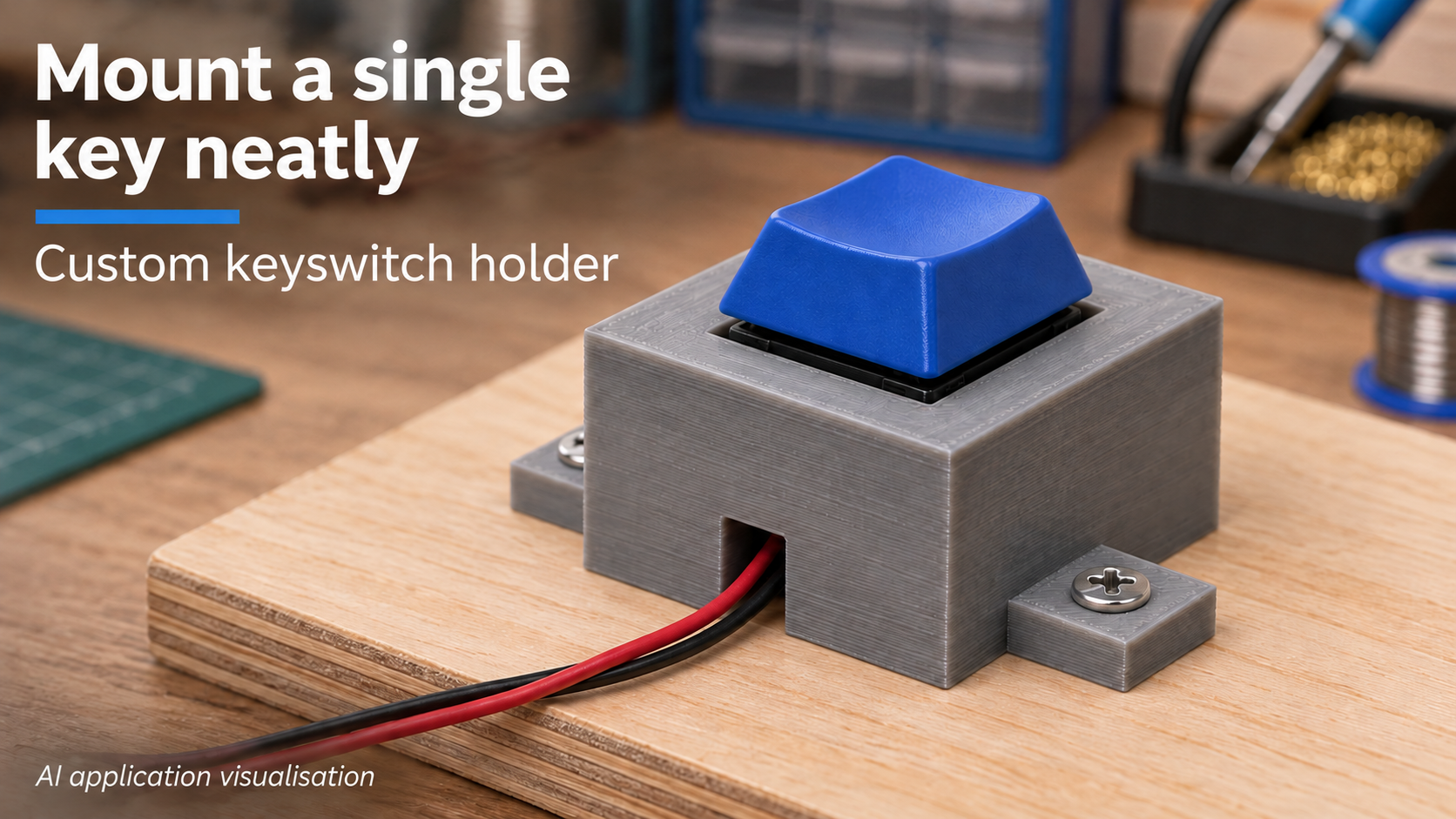
A printed holder uses a thin retaining plate for a compatible keyswitch. Two feet secure it to your base, while an open-bottom notch routes the wires out.
One stable key for an input prototype
A small input experiment may need just one keyboard switch fixed to a base. A loose switch is awkward to press consistently, while a full keyboard plate is excessive for a single key. This holder provides a rectangular opening in a thin upper plate. Compatible side clips on the switch engage behind that plate.
A larger space beneath clears the switch body and contacts. Two opposing feet fasten the holder to your support. An open-bottom notch routes connection wires out of the body cavity. The switch, keycap, electronics and fixing screws are separate; the printed holder does not itself provide an electronic input function.
Match both the opening and retaining-plate thickness
Opening width and depth each adjust from 10 to 22 mm. The starting size is 14.2 × 14.2 mm, but this does not guarantee a brand fit. Measure your switch or check its required plate cut-out. Allow for printing variation without enlarging the opening until the clips lose their grip.
Retaining-plate thickness adjusts from 1.2 to 3 mm, with a 1.5 mm default. It must match the clip geometry. A plate that is too thick may prevent engagement; one that is too thin may allow movement. Test the fit on a print and insert the switch without force. Not every switch has compatible side clips.
Leave room for the body, contacts and wires
Body clearance height adjusts from 8 to 22 mm, initially 12 mm, with the retaining plate added above. The internal cavity is 6 mm larger in each direction than the corresponding upper opening. Still check your actual switch body, contacts and intended wire routing: this fixed extra clearance cannot replace measuring the components.
Wall thickness ranges from 2 to 4 mm. Cable-notch width ranges from 3 to 10 mm, and its nominal height is half the body-clearance height. It is open at the bottom and is not a cable gland or strain relief. Keep wires away from surfaces that could trap them between the holder and base when tightening.
Prepare the print and mounting
Print on the upper retaining-plate face so the larger cavity grows upward and stays open. Check the opening edge for print residue and first-layer expansion. Remove only unwanted material rather than weakening the retaining edge.
Foot holes adjust from 2.5 to 5 mm, initially 3.4 mm. Default settings produce a 25 × 25 mm main body, 13.5 mm tall, with feet extending total width to 41.4 mm. Select screws for your base. With the switch and your keycap fitted, check that the full key travel remains unobstructed and the switch stays seated.
An open holder for a low-voltage project
The underside remains open. Insulate contacts separately; this is not a tested electrical protective enclosure. Use it only in the intended low-voltage setup. Wiring and input processing depend on your own project and are not supplied by the STL.
The image is an AI application visualisation of an assembled input prototype. No physical test prints or brand-compatibility tests have been performed. After checking the fit yourself, create the STL or use the manufacturing option available on the model page.
Next step