


Hobby mechanics & mounting ·
Mount a small hobby servo on a workbench with a raised flange bracket
The open bridge supports a servo by its two mounting ears while keeping the case underside and cable accessible beneath the upper frame.
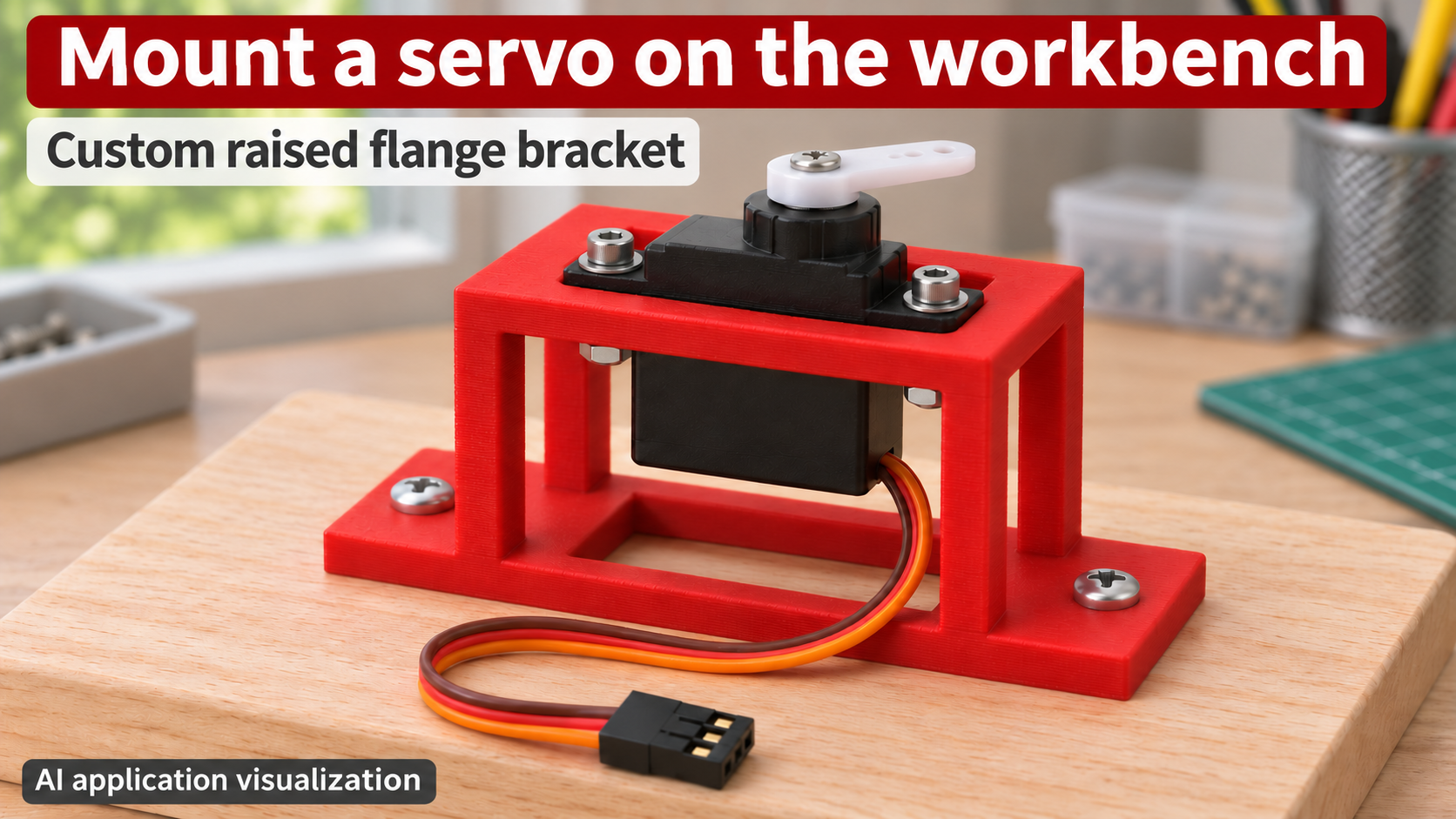
A clear layout for a small servo
A light tabletop demonstration needs the hobby servo held still while its underside, cable and horn remain accessible. This raised bridge supports the mounting ears on a rectangular upper frame. Four corner posts connect it to the base plate, with an open window below the body.
The image shows mechanical assembly before connection: the three-pin plug rests unplugged on the board and the horn carries no load. Servo, horn, bolts, nuts and wood are separate from the printed part. The AI visualization is not evidence of a physical functional test.
Check the actual flange pattern
This bracket is intended for a servo with one central mounting hole at each end of its case. Four-hole flanges, offset holes and other case shapes are not automatically compatible. Measure the length and width of the portion that must pass through the window, including projecting edges.
body_l and body_w describe that case. fit is added once to the whole window length and once to its whole width, not per side. A 23 × 13 mm case with fit = 0.4 mm gives a 23.4 × 13.4 mm window. The mounting ears must still have adequate support.
Use the correct hole and height references
ear_offset measures from each case end to the mounting-hole centre. The servo-hole pitch is body_l + 2 × ear_offset, giving 31 mm from 23 mm and 4 mm. Clearance enlarges the window without changing this pitch. servo_d = 2.4 mm sets the two through-hole diameters.
clear_h = 24 mm places the underside of the upper frame 24 mm above the mounting underside. With wall = 3 mm, its top surface, where the ears rest, is 27 mm high. Measure case depth below the ears from that seating plane and allow clearance above the actual table surface plus room for the cable exit.
Outside the window there is 21 mm between the base plate’s top and the upper frame. The open lower window removes printed material only; it does not remove a wooden board underneath. A deeper case must therefore still clear that board.
Plan two servo fixings and two base fixings
The default upper frame is 39.4 × 19.4 mm. Overall base length is 58.2 mm, with its two mounting holes 48.8 mm apart. base_d = 3.4 mm applies to these holes independently of the smaller servo holes.
Lower the servo through the window without force, seat its ears flat and use suitable bolts, washers and nuts. Check clearance for nuts beneath the ring and tool access between posts. Do not bend the ears or crush the plastic by overtightening. Secure both outer feet to a sound, flat support.
Print and inspect before connecting power
Prepare the print on its base. The upper bridge may need supports; inspect the layer preview and remove support remnants fully from the window and bores. Check posts, flange faces and cable passages for burrs.
Keep the horn’s movement envelope clear and route the lead without tension or contact with moving parts. Follow the actual servo’s requirements for any later connection; the bracket has no electrical function. It is intended for light tabletop models, not vehicles, aircraft or protective functions. No particular holding force or physical validation is guaranteed.
Next step