


3D printing and filament guides ·
Keep a cool PTFE filament coupling collar raised with a printed clip
A flat C-clip fills the space beneath a raised release collar to prevent accidental downward movement. Measure the fitting neck and available height before choosing dimensions.
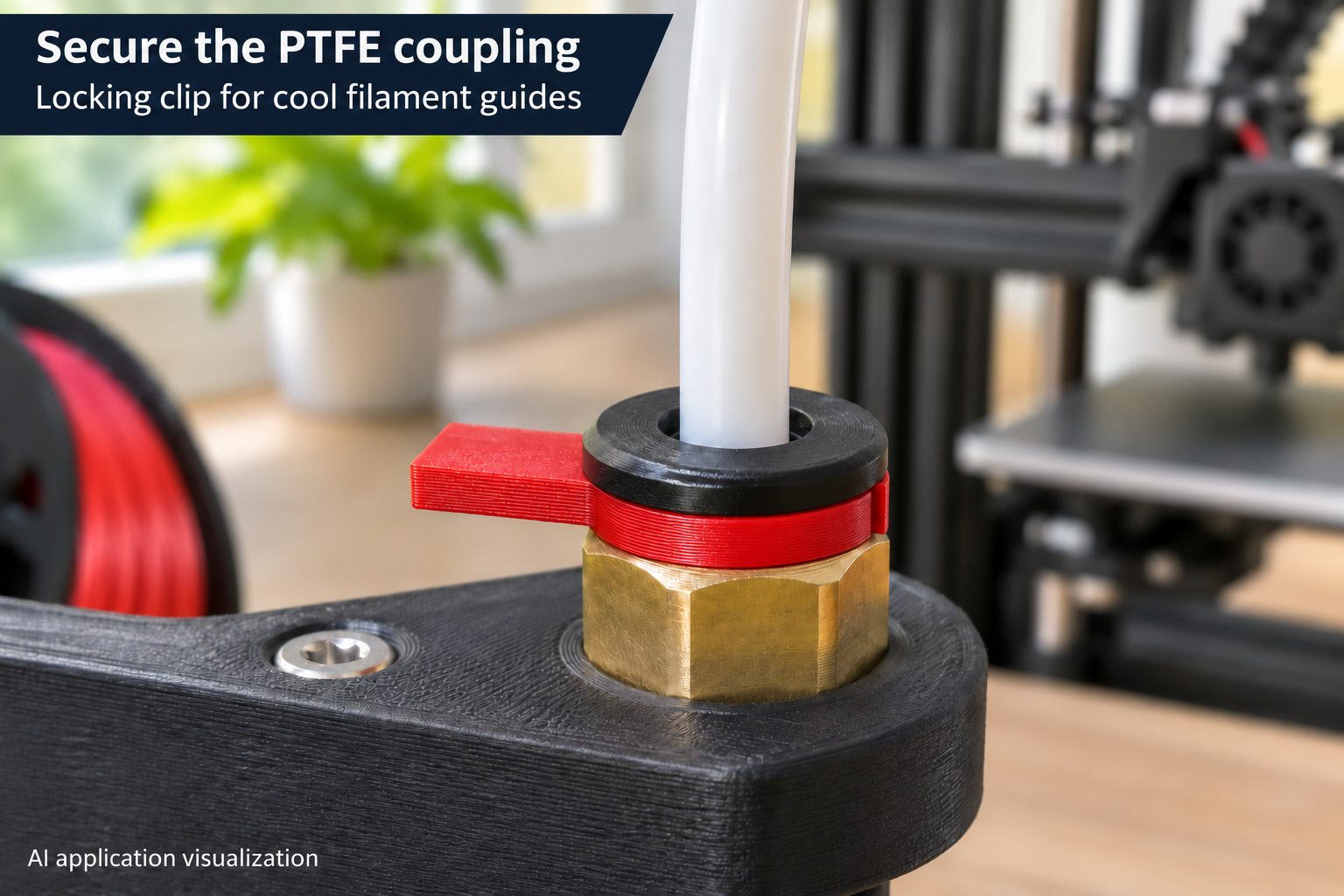
Hold the release collar in its operating position
On a compatible push-fit coupling, pressing the release collar down allows the PTFE tube to be removed. During use, the collar should stay raised. This side-entry clip occupies the clearance beneath it, while a rectangular pull tab remains accessible for removal.
The clip belongs around the narrow neck below the collar, not on top of the collar or around the exposed tube. Its intended use is a cool filament guide or the cool extruder end. It does not replace the gripping teeth inside the fitting or repair a damaged tube.
Measure the fitting neck rather than the tube
Measure the exposed neck and the axial clearance between the fitting body and raised collar. Neck diameter adjusts from 3 to 12 mm, initially 6 mm. Outside diameter is 7–20 mm, starting at 11 mm. It must be at least 3 mm larger than the neck diameter while clearing nearby components.
Clip thickness is adjustable from 0.8 to 3 mm, with 1.5 mm as the default. It must fit the measured space without forcing the collar upwards. Account for printing tolerance in your selected dimensions; the model has no separate fit-allowance parameter.
Size the entry gap and pull tab
The entry gap ranges from 2 to 10 mm and starts at 4.8 mm. It must also be smaller than the neck diameter and greater than 60 percent of that diameter. These constraints retain a side-entry C shape; the individual parameter limits cannot be combined arbitrarily.
The rectangular tab is opposite the opening. Its length is 4–18 mm and its width 3–10 mm, initially 8 and 5 mm. Tab width must remain below the outside diameter. Leave enough room to grip it without catching moving printer components.
Install and check the tube retention
Print the flat part in the tough PETG specified for this application and remove burrs around the opening. Insert the tube according to the existing fitting instructions, raise the collar into its holding position and slide the clip underneath from the side. It must not crack, pinch the tube or force the collar.
Check that both tube and clip remain secure on your own assembly before operation. For removal, take out the clip first, then operate the collar as instructed for the fitting. Keep it away from heater blocks and do not use it on compressed-air or liquid lines. Replace worn coupling components instead of masking the problem. The picture is an AI application visualization; no physical test prints have been performed.
Next step