


Electronics and controls ·
Mount a potentiometer on a prototype board with an anti-rotation bracket
Give a rotary potentiometer a fixed place in a bench experiment. This open bracket supports its threaded bushing and existing locating pin while leaving room for terminals.
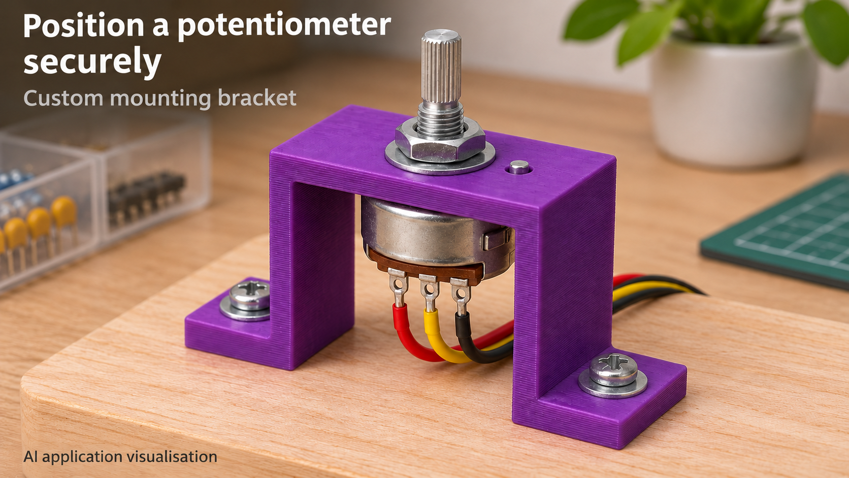
Hold a control in a low-voltage experiment
A loose rotary potentiometer is awkward to operate if its body turns and moves the leads. This open bracket places two side feet on a mounting board. The potentiometer body sits below the top bridge and its threaded bushing passes through the central bore. Its own nut and suitable washer secure the bushing to the bracket.
A second, smaller hole accepts the existing anti-rotation pin. The model supplies no pin and contains no printed thread. Potentiometer, nut, washers, foot screws and wires are separate items. The application is a current-limited low-voltage hobby setup.
Measure the bushing and locating pin
bush_d is finished clearance for the threaded bushing, not the rotating shaft diameter. Measure over the bushing thread and allow for printing clearance. Also check usable bushing length: the bridge thickness, washer and nut must fit while leaving adequate thread engagement.
pin_offset is measured from bushing centre to pin centre; pin_d is the finished hole diameter. The pin hole lies to one side on the same depth centreline. A flat or differently shaped locating tab does not necessarily fit just because its width is below pin_d. Check shape, position and length on the actual component.
Allow space below the bridge
body_w is the clear distance between the side walls. clear_h runs from the floor to the underside of the bridge. Both dimensions must accommodate the body, terminals and wire bends. The bracket is open front and rear; its depth is not an enclosure dimension.
Defaults are bush_d 7.3 mm, pin_d 2.3 mm, pin_offset 9 mm, body_w 27 mm, clear_h 24 mm, wall 3 mm and base_d 3.4 mm. Bracket depth is bush_d plus twice wall plus 4 mm, or 17.3 mm. Total height is clear_h plus wall, 27 mm. Overall width including both feet is 51.8 mm.
Choose compatible settings
Ranges are bushing bore 5–12 mm, pin hole 1.5–4 mm, pin offset 6–16 mm, clear width 18–45 mm, clear height 14–40 mm, wall 2.4–5 mm and foot bore 2.5–5 mm. Pin offset must exceed half the sum of bush_d and pin_d plus 1 mm so the openings remain separate.
body_w must exceed twice pin_offset plus pin_d plus 2 mm. A large pin offset can therefore require more clear width. Each foot projects by base_d plus twice wall; increasing the foot bore also widens the feet. Check that the nut and washer do not unintentionally cover the pin hole.
Assemble and check body rotation
One possible print orientation is top face down; the feet may need supports. Deburr the fits and insert the potentiometer from below. Bushing and pin must enter together without force. Tighten the nut carefully without distorting the plastic or body. Attach the feet to a flat board with suitable screws and washers.
Connect and insulate the leads separately, provide strain relief and keep soldering heat away from the plastic. Turn the shaft gently through its intended range and check that the body remains fixed without pulling a wire tight. The image deliberately omits the knob to show the attachment. This open bracket is not a mains-voltage insulating enclosure. The image is an AI application visualisation; no physical print or endurance test is documented.
Next step