


Workshop and frame making ·
Guide a band clamp around a polygon frame with custom corner pads
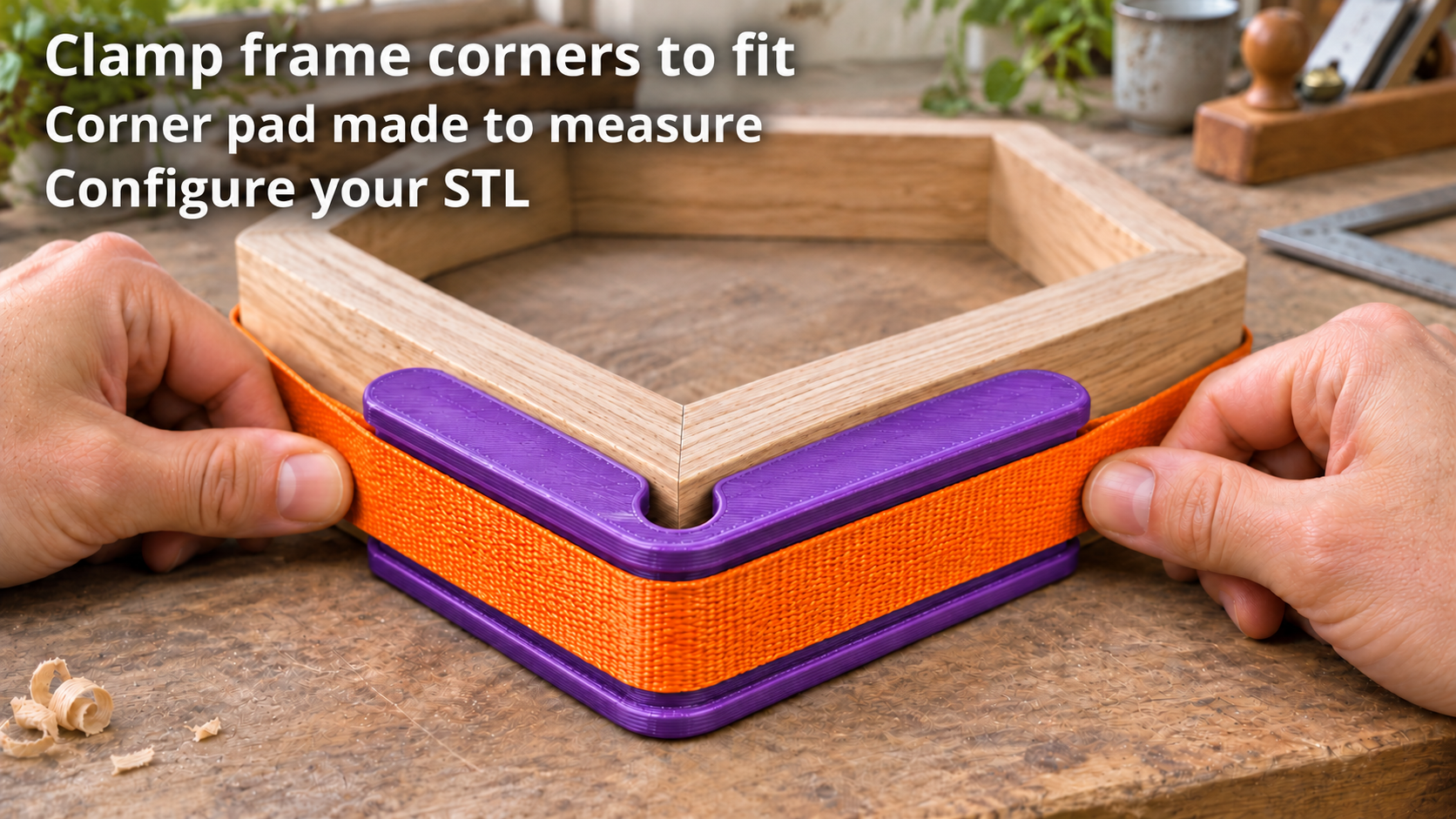
Match the pad’s fixed inside angle to your frame corner. Two contact arms sit outside the wood, while the surrounding strap runs between guide flanges.
Guide the strap around a frame corner
During a polygonal wooden frame glue-up, the strap needs to follow the outside contour. This pad rests against the outside faces of two adjoining frame members. The strap runs around its back between upper and lower guide flanges. An open relief leaves clearance around the delicate wood vertex.
The model creates one fixed-angle pad, not an adjustable mechanism. A complete frame needs suitable pads at all corners and a separate strap. Check existing band-clamp corners first, as some already accommodate different angles.
Measure the finished frame’s interior angle
The inside angle can be set from 60 to 150 degrees, initially 120 degrees as on a regular hexagon. Measure the actual frame angle rather than entering one member’s mitre cutting angle. Contact arm length ranges from 20 to 55 mm, starting at 30 mm.
Clear strap-guide height is 10–40 mm, initially 20 mm. Add clearance beyond the strap’s actual width. Material behind the contact faces is 5–10 mm thick. Guide flanges are 1.6–4 mm high and project 1–3 mm. Choose these dimensions together so the strap lies flat without riding over a flange.
Trial-fit the complete assembly before gluing
Corner relief radius ranges from 1 to 5 mm but must leave at least 3 mm relative to the wall setting: radius must not exceed wall thickness minus 3 mm. Defaults are 6 mm wall, 2 mm relief, 2 mm flange height and 2 mm projection.
Print in PETG with five perimeters and high infill, resting on the lower flange. Check the upper overhang and layer bonding around the corner. Assemble all pads without glue first, route the strap outside and tension gently by hand. This is for cautious glue-up clamping only. No load rating is established, and it is not for lifting, transport or securing cargo.
The image is an AI application visualization, not a photograph of a physically tested print. Accessories shown are not included in the STL.
Next step