


Electronics ·
Slide a PCB into an enclosure with custom opposed guide rails
A pair of printed rails guides clear circuit-board edges and provides a rear stop, making a small low-voltage hobby board easier to remove for access.
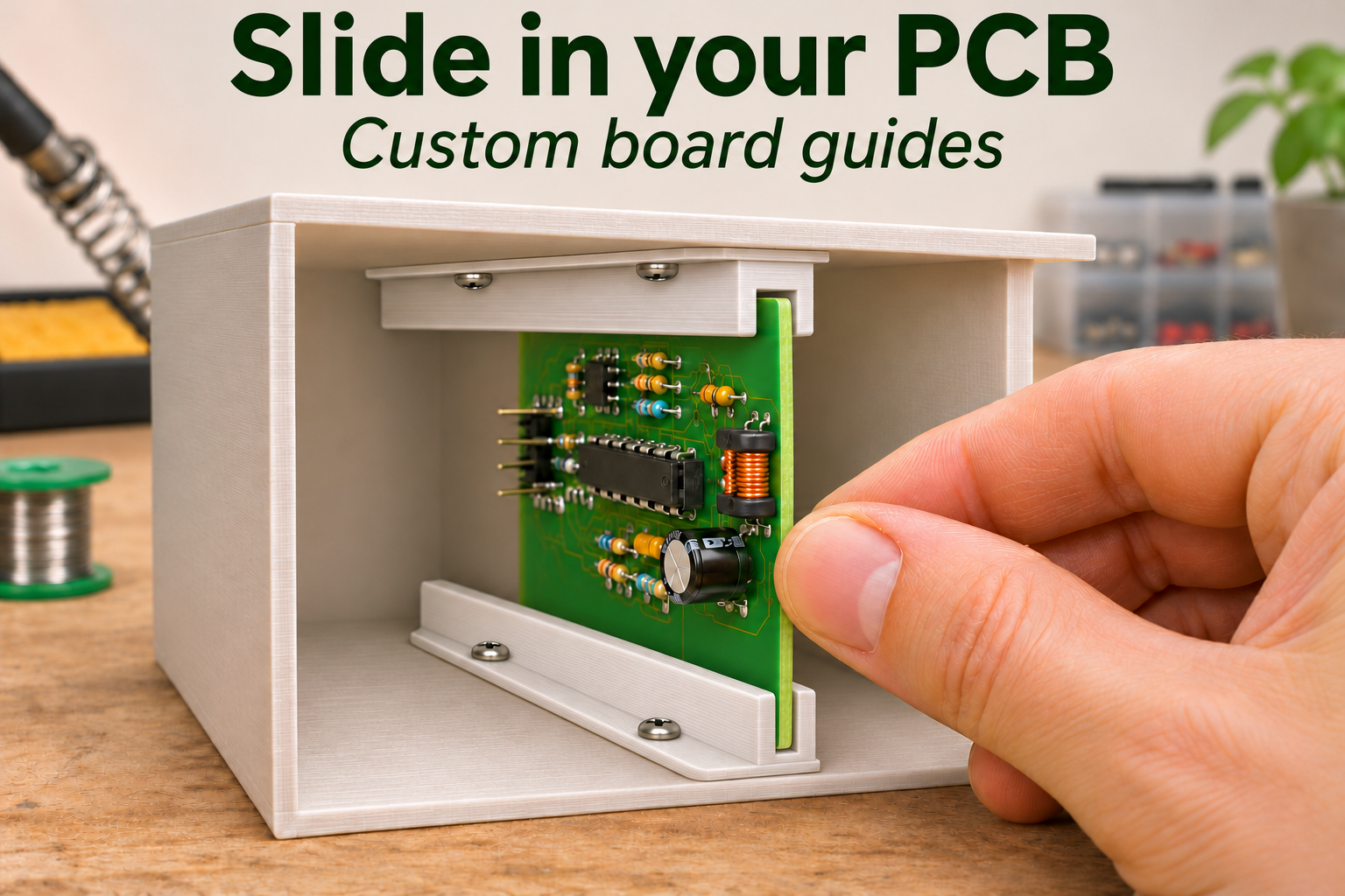
Guide a removable circuit board
A small hobby enclosure often needs a circuit board that can be removed for changes. This pair of rails guides two opposite component-free edges and provides a closed rear stop. In the illustrated arrangement the board stands vertically. The lower slot opens upward, while the upper rail is inverted so its slot opens downward. Both open ends face the enclosure opening.
Each rail has a side mounting flange with two screw holes. The lower flange sits on the enclosure floor and the upper flange against the underside of its roof. Fasteners pass through these flanges, not through the slot walls. The rear stop limits insertion but does not prevent withdrawal. Add a separate removable front restraint to the enclosure where needed.
Measure thickness and available space
Measure actual board thickness, including the finish along the guided edges. The thickness parameter ranges from 0.8 to 3.2 mm, with an additional total slot clearance of 0.2 to 0.8 mm. A 1.6 mm board with 0.4 mm clearance gives a nominal 2.0 mm slot. This calculation does not validate printer accuracy; a short fit sample is useful before printing the complete rails.
Rail length can be 35–180 mm and edge engagement 2–8 mm. Wall thickness of 1.6–4 mm and flange width of 6–16 mm affect the required space. Screw pitch ranges from 20 to 150 mm but must fit the chosen rail length. The design checks end margins, so not every combination of individual limits can be used together.
Check alignment before powering the board
Print with the flat base and flange on the build plate, then inspect the slots for burrs and strings. Avoid sharp contact surfaces against solder mask or tracks. Both board edges need a sufficiently wide clear margin; components, solder joints and connectors must remain outside the grooves. Choose fasteners that fit the flange holes without distorting the rails.
Mount the pair parallel and set their separation from the actual board height and required engagement. Slide the board in with power disconnected, checking that cables and connectors remain accessible. It should move without bending. This guide is intended for small low-voltage hobby assemblies. It does not replace assessed electrical insulation, fire protection or EMC design, and no universal board fit or physical print test is claimed.
The image is an AI application visualization, not a photograph of a physically tested print. Accessories shown are not included in the STL.
Next step