


Electronics ·
Attach an encoder magnet to a shaft with a printed split clamp hub
An adjustable hub carries a disc magnet on a small shaft for a slow, hand-turned encoder experiment while the sensor remains independently fixed.
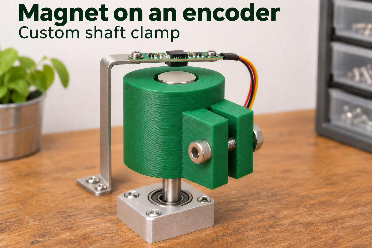
Rotate the magnet while keeping the sensor fixed
A small encoder learning project needs a magnet to rotate with a shaft while its sensor stays still. This printed hub has a shaft socket underneath and a circular disc-magnet pocket on top. A split lower section with two clamping ears tightens around the shaft using a separate screw and nut. The magnet, sensor, shaft and bearings are additional components.
A solid web separates the blind shaft socket from the magnet pocket. The shaft therefore does not pass through the magnet. Mount the sensor on its own rigid support attached to the stationary base, never to the rotating hub. In the illustrated setup, the sensor board sits above the magnet with an air gap and clearance from the side clamp.
Size the shaft bore and magnet pocket
Shaft diameter is adjustable from 3 to 10 mm and insertion depth from 8 to 22 mm. Measure your actual shaft and account for printing fit in the selected bore diameter. The hub should slide on before tightening. Its fixed 1.2 mm slit is not a guarantee that the clamp can absorb arbitrary dimensional errors.
The magnet pocket accepts a configured diameter of 4–12 mm and depth of 1.5–6 mm. Use the magnet type and magnetization required by your sensor; a suitable angular sensor may require a diametrically magnetized disc. Allow for the actual magnet height and any bonding clearance. Wall thickness of 2.5–5 mm and separating web thickness of 1.5–4 mm also affect the hub's overall size.
Assemble and inspect at hand speed
Inspect the printed bore, slit, clamping ears and nut seat. Screw-hole diameter ranges from 2.4 to 4.4 mm and nut width across flats from 4.5 to 8 mm; geometric minimum-spacing checks restrict their combinations. Use matching hardware and tighten only enough to retain the hub, without forcing the ears together or cracking the print.
Secure the magnet using a suitable separate bonding method and allow it to cure. Align the sensor axis, magnet center and air gap according to the chosen sensor's requirements. Turn the shaft slowly by hand and check clearance around the hub, clamp screw, bracket and wiring. Runout, signal behavior and calibration must be checked on the complete assembly. This is a slow experimental setup, not a high-speed motor attachment or a safety-related control component. No measured accuracy or physical print validation is claimed.
The image is an AI application visualization, not a photograph of a physically tested print. Accessories shown are not included in the STL.
Next step