


Mechanisms and hobby projects ·
Guide a light compression spring between two telescopic printed seats
A tube and mating pin guide your own spring from the inside. Size the seats for the spring and plan sufficient overlap plus a separate travel stop.
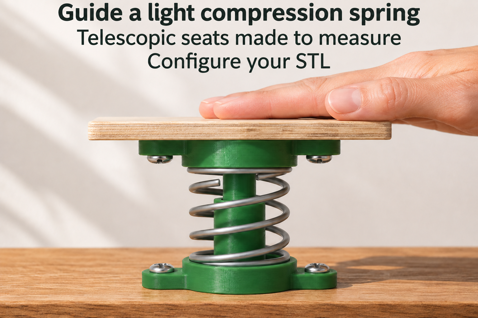
Locate the spring between two seats
A weak compression spring can provide a small return action in a hobby assembly. The lower printed seat carries a guide tube; the upper seat has a mating pin and short centring boss. Your own metal spring surrounds this internal guide. Low perimeter lips locate its ends on the two seats.
Both parts print side by side and are turned to face one another during assembly. Each seat has two lateral screw ears. The set includes neither the spring nor a mechanism retaining the halves when pulled apart. Plan the overall motion guidance and movement limits separately.
Match spring measurements and guide dimensions
Measure the spring inside and outside diameters. Available ranges are 8–22 mm inside and 11–28 mm outside, initially 12 and 16 mm. Guide-tube outside diameter is constructed 0.8 mm smaller than the entered spring inside diameter. Check clearance during movement as well as at an unloaded spring end.
Guide length ranges from 12 to 32 mm, initially 18 mm. Pin diameter ranges from 4 to 12 mm, initially 6 mm. Clearance of 0.2–0.8 mm, initially 0.4 mm, is added once to pin diameter to determine the tube bore. The chosen combination must leave enough wall around that bore.
Set the allowed travel before use
Maintain at least 5 mm guide overlap with the spring installed. At the same time, the gap between the facing spring-seat surfaces must remain greater than guide length plus 2 mm. An 18 mm guide therefore needs more than 20 mm seat spacing. Spring solid height and permitted compression may impose additional limits; the printed guide is not a travel stop.
Floor thickness and rim width range from 2.5–5 and 3–7 mm, starting at 3 and 4 mm. Mounting holes range from 2.4 to 5.4 mm, initially 3.4 mm. Smooth tube and pin, test sliding without the spring first and align the seats during mounting. Use only weak springs that can be compressed by hand and move slowly. Stop if the guide binds rather than applying greater force.
The image is an AI application visualization, not a photograph of a physically tested print. Accessories shown are not included in the STL.
Next step