


Hobby mechanics & cable routing ·
Secure a light cable chain with a clevis end anchor and adjustable foot
Hold a suitable terminal link between two cheeks on a through axle. Two lengthwise mounting slots help align it on a flat support surface.
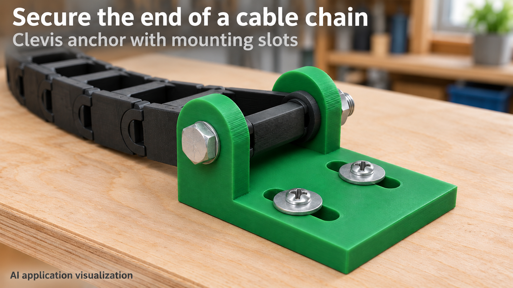
Align the end of a small cable chain
A slow, lightweight hobby assembly needs the last chain link to match its mounting surface. This end anchor forms a fork with two side cheeks. Your own through-bolt or axle joins them to a suitable cross-axis bore in the terminal link. Two slots in the forward foot allow lengthwise alignment.
The image shows a mechanical trial fit with an empty chain. Chain, axle, nut, washers and mounting screws are separate components. This is an AI application visualization, not evidence of a printed or moving prototype.
Check the terminal link before choosing dimensions
The model requires a terminal link with a suitable continuous cross-bore. Side snap pins and proprietary closed connections are not automatically compatible. Measure the full width of the captured section and include the desired sideways clearance directly in fork_gap. There is no separate fit parameter.
Check where the axle runs inside the terminal link. It must not cross the later cable route, pinch conductors or create a sharp contact point. The illustrated trial is performed without cables. Cable exit, bend radius and any separate strain relief must then be matched to the actual assembly.
Measure axle height from the correct surface
axis_h is the height of the axle centre above the underside of the mounting foot. At 12 mm axle height and 3.5 mm foot thickness, the centre is therefore 8.5 mm above the foot’s upper surface. Check the link’s moving envelope as well as its resting height.
With fork_gap = 20 mm and wall = 3.5 mm, overall width is 27 mm. At pin_d = 3.4 mm, the rounded cheek radius is 5.2 mm and overall height is 17.2 mm. foot_l = 28 mm measures forward from the axle centre; including the rear radius, the base is 33.2 mm long. These dimensions do not establish universal chain compatibility.
Align the slots, then tighten the fixings
mount_d = 4.4 mm sets slot width. travel = 9 mm is the distance between the rounded end centres, so total slot length is 13.4 mm. Actual screw travel also depends on its shank diameter. Both slots run along the foot, not across it.
The default slot centres are 14 mm forward of the axle and 15.6 mm apart. Choose suitable screws with washers that bear adequately on the foot and use a sound mounting surface. Loosen both screws to align the anchor, then tighten them. The slots provide installation adjustment, not a sliding guide during operation.
Retain the axle and test without load
Choose axle length for the whole fork width plus washers and retention hardware. The nut must not squeeze the cheeks together enough to bind the terminal link. Check the required freedom of movement and secure the axle against migration. A nominal screw size alone does not establish a suitable joint.
Print on the flat underside. Inspect the horizontal axle bores in the slicer and carefully finish them if necessary without damaging the cheeks. Move the empty chain slowly by hand through the intended path, checking contact with the foot, cheeks and screws.
Use only for light, slow hobby assemblies after your own checks. This anchor is not machine guarding or a validated fastening for heavy moving cable bundles. Set all seven parameters around the actual terminal link and support surface.
Next step