


Covers and fasteners ·
Align a light cover with a custom floating nut cassette
A captured hex nut can accommodate a small hole offset. Size this printed cassette for the actual nut, screw and support behind your removable cover.
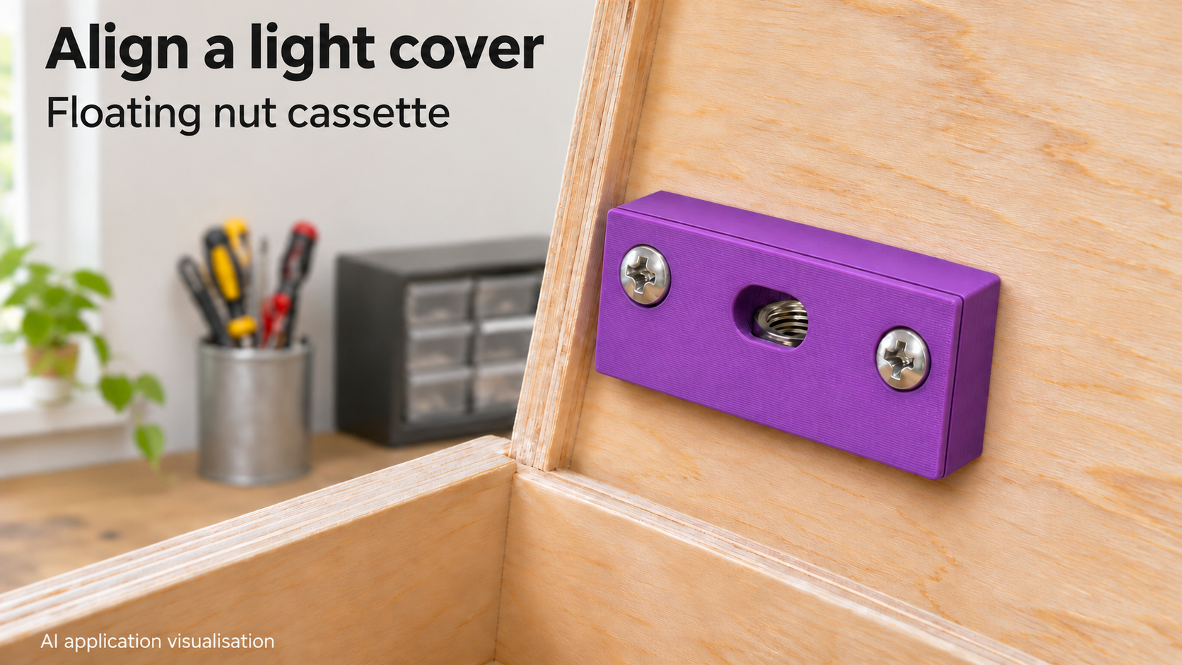
When the cover screw just misses its thread
A small offset between a light indoor cover and its fixing point can make assembly awkward. Once a nut has been glued rigidly in place, it cannot follow the screw. This two-piece cassette captures a separate hex nut while allowing limited sideways movement. It can accommodate the offset only when that offset falls within the available clearance.
The rectangular pocket limits nut rotation. A base and lid retain the nut axially, and two outer screws fasten the complete cassette to your support. There are no printed threads. Supply the nut, matching threaded screw and suitable mounting hardware separately.
Measure the real nut before choosing the travel
Measure the nut across its flats and its actual height. The width setting includes your chosen fit allowance; it ranges from 5.5 to 13 mm. Nut height ranges from 2.5 to 7 mm. Do not infer a standard thread size from the default dimensions: the nut must match the screw thread as well as fit the printed pocket.
Longitudinal travel is adjustable from 0.3 to 2 mm and transverse travel from 0.2 to 1.2 mm. Each setting describes the total intended travel, not travel to either side. Clearance added to the nut width and printing variation affect the actual movement. The pocket’s narrow side must remain smaller than the real nut’s width across corners to prevent a complete turn.
Allow space for both the cassette and the moving screw
Central screw clearance ranges from 2.5 to 7 mm. The opening is extended in both directions by the selected travel. The configurator rejects combinations that make the opening too wide to retain the nut or allow excessive transverse movement. These geometric checks do not replace a fit check with your own hardware.
With the defaults of 8.2 mm nut width, 4 mm nut height, 1 mm longitudinal travel, 0.6 mm transverse travel and 2.4 mm wall thickness, the assembled cassette is approximately 31.7 × 13.6 × 9.1 mm. Reserve that space behind the cover. The hole in the supporting structure must also allow the screw to move; a tight hole behind the cassette would defeat the floating action.
Print, insert the nut and check free movement
Print both pieces on their flat outer faces. Remove debris from the pocket and openings without unnecessarily enlarging the nut guide. Insert the nut into the base and close the lid. The model includes 0.3 mm of additional vertical space above the configured nut height. Check that the actual printed assembly still allows the nut to move after closing.
Outer mounting holes adjust from 2.5 to 5 mm and wall thickness from 2 to 4 mm. Select mounting screws for your support and tighten without deforming the plastic. Offer up the cover and start its central screw by hand. It should engage without cross-threading; resistance is a reason to check alignment and clearance before tightening further.
A small alignment aid for light indoor covers
This cassette is intended for small positioning corrections. It is not a rated metal threaded fixing, and no clamping force is specified. Increasing tightening force will not correct an excessive hole offset. Check the material, support, screw length and thread engagement on your own assembly.
The image is an AI application visualisation showing the installed cassette with the cover removed. No physical test print or load test has been performed. Once the dimensions are checked, create the STL for your own printer or use the manufacturing option available on the model page.
Next step