


Model railway and workshop ·
Mount your own flat-bottom model railway rails in fitted screw-down chairs
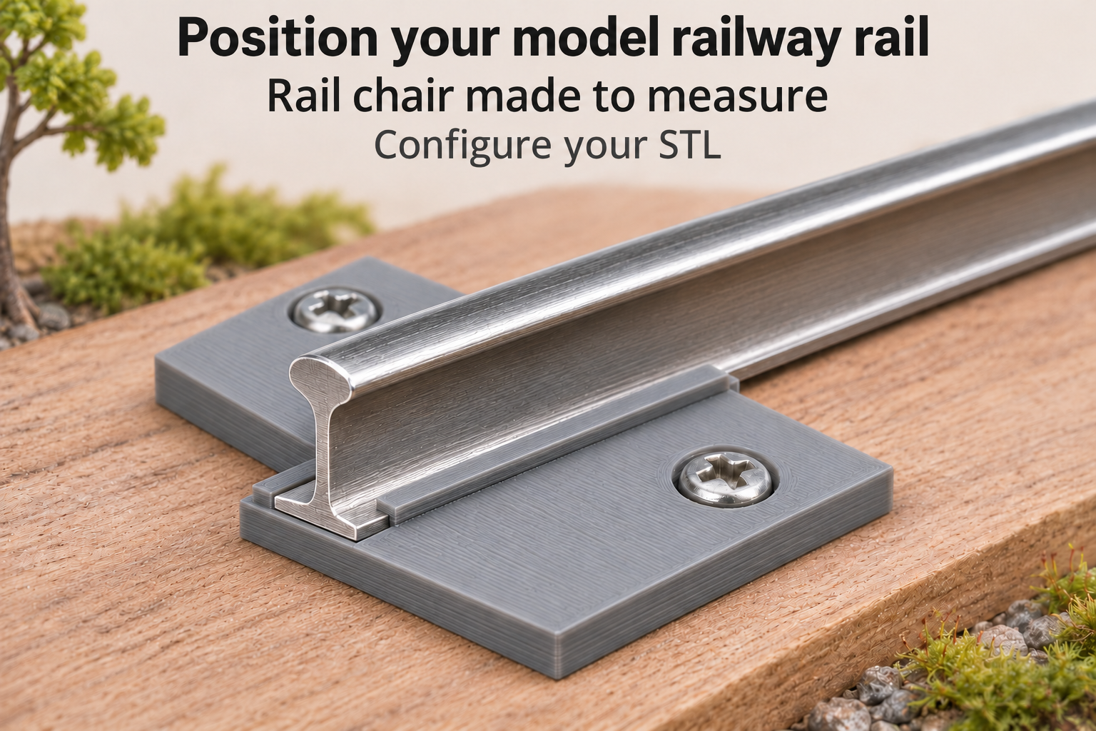
Slide the rail foot under two retaining ledges, size the channel around its actual cross-section and screw the chair to your baseboard.
Locate a rail on your own baseboard
A small display or test track needs its individual rail profiles held at defined positions. This chair guides the broad rail foot in a continuous channel. Two retaining ledges overlap the foot while the narrower vertical web passes through the central opening. Two side screws attach the base to your board.
Both ends of the channel are open. Slide the chair onto a free rail end before final assembly. It is not a snap-on clip to push down over the rail head. Joining rail ends and setting the track gauge remain separate tasks.
Measure more than overall rail height
Measure foot width and thickness, then the web width where the retaining ledges will sit. Finished foot-channel width ranges from 3 to 12 mm, channel height from 0.6 to 3 mm and web opening from 1.2 to 6 mm. Starting values are 6.4, 1.3 and 2.8 mm. Include the required print clearance within these channel dimensions.
Ledge thickness ranges from 0.6 to 2.5 mm, initially 1.2 mm. The top of each ledge must stay below the underside of the rail head. Matching total profile height is therefore insufficient. Keep enough overlap on the foot: the construction requires channel width to exceed the web opening by more than 1.4 mm.
Plan fastening and check one print
Chair length ranges from 8 to 30 mm and base thickness from 1.8 to 5 mm, starting at 14 and 2.5 mm. Screw clearance can be 2.2–5.4 mm and mounting centres 14–40 mm; defaults are 3.4 and 22.5 mm. Screw heads need clearance beside the rail and must not obstruct its foot.
Inspect the overhanging ledges in the slicer and remove any support residue from the channel. Try one chair on a deburred spare profile first. Tighten the mounting screws without warping the base and align successive supports. Establish gauge and electrical isolation separately. This is for small model railway displays and tests, not passenger-carrying railways.
The image is an AI application visualization, not a photograph of a physically tested print. Accessories shown are not included in the STL.
Next step