


Electronics and displays ·
Fit a display PCB into a prototype panel with a window frame and rear ring
Give a small display a neat position in a prototype front panel. A front PCB seat and separate retaining ring capture the board at clear edge areas.
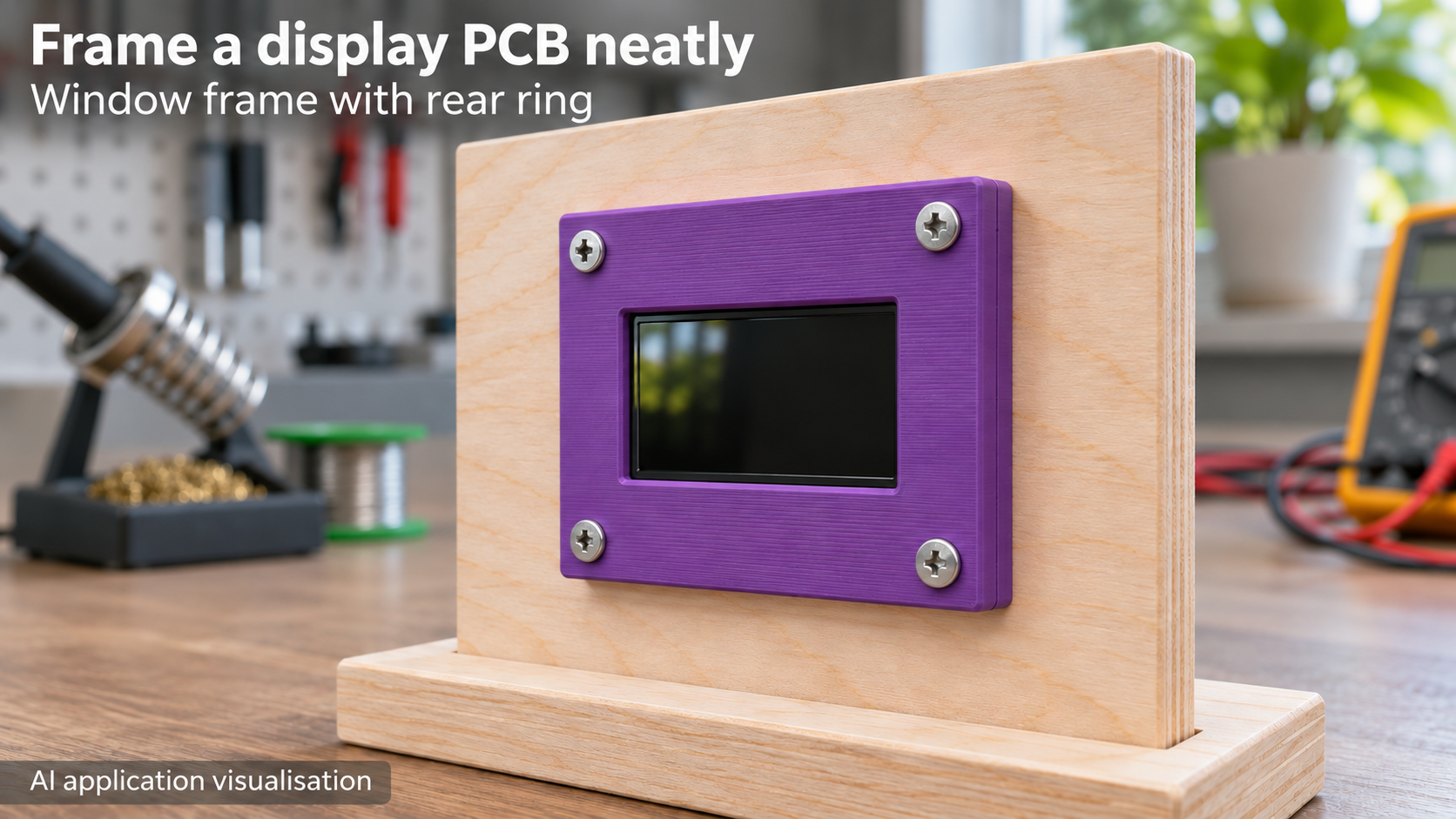
Integrate a display mechanically into a prototype panel
A small display PCB needs to sit in a panel without using its glass as a mounting surface. The front frame has a rectangular opening and a surrounding PCB seat behind it. A separate rear ring limits backward movement. Four holes outside the PCB join the printed parts and can also secure them to a suitable panel.
The illustrated use is a small, unpowered display in a wooden prototype front. Display electronics, screws, panel and any additional seating pads are separate items. This model is neither a complete enclosure nor electrical insulation.
Measure the complete display assembly
pcb_w and pcb_h are PCB outside width and height; pcb_t is its thickness at the support areas. window_w and window_h must suit the entire protruding display package, not just the lit or printed image area. Glass borders, a metal surround or adhesive margin can be substantially larger than the visible display.
The front needs at least 2 mm of component-free PCB support around the cutout. The rear ring also needs clear outer edge strips. Check both PCB faces for components, solder joints, connectors and traces. Neither glass nor components should carry frame pressure. The openings are centred, so an offset display does not automatically fit.
Clearance does not automatically produce clamping
Defaults are pcb_w 30 mm, pcb_h 28 mm, window_w 24 mm, window_h 14 mm, pcb_t 1.6 mm, wall 2.6 mm, mount_d 2.4 mm and fit 0.3 mm. The PCB seat adds fit once to its width and height, producing 30.3 × 28.3 mm. Seat depth is pcb_t plus fit, or 1.9 mm.
An actual 1.6 mm PCB therefore retains a nominal 0.3 mm thickness-direction gap when the frame faces meet fully. The rear ring captures the board but does not automatically clamp it without play. Do not try to remove this gap by overtightening. If needed for your assembly, provide separate suitable seating pads only on clear PCB edges and check their thickness.
Rear opening, outside size and adjustment ranges
The rear opening is pcb_w minus 4 mm by pcb_h minus 4 mm, giving 26 × 24 mm. A centred board nominally overlaps it by 2 mm on each outer edge; lateral clearance can alter the distribution. This rear opening is independent of the window dimensions and must clear the rear components.
Ranges are PCB width 22–65 mm, height 20–60 mm, window width 14–55 mm, window height 8–45 mm, PCB thickness 1–3 mm, frame thickness 2–4 mm, screw bore 2–4 mm and fit 0.2–0.7 mm. Each window dimension must remain at least 4 mm smaller than its corresponding board dimension.
Outer border width is mount_d plus twice wall. Both parts default to 45.5 × 43.5 mm externally; the front is 4.5 mm thick and the rear ring 2.6 mm. Combined thickness is 7.1 mm without a mounting panel. Increasing screw bore diameter also increases outside dimensions.
Assemble without stressing glass or PCB
Print both parts flat and deburr the seats and holes. Lay the PCB into the front seat without force, add the rear ring and tighten four suitable screws evenly. The holes lie outside the board; they do not drill through it. Match screw length and opposing fastening to the frame stack and panel.
For panel mounting, provide a suitable rear cutout for electronics and connectors. Do not trap cables beneath the retaining ring. Before powering up, check retention, remaining play, glass-edge clearance and component spacing. The frame establishes no impact, moisture or electrical protection rating. The image is an AI application visualisation; no physical print or operation test is documented.
Next step