


Hobby electronics & mounting ·
Mount a small hobby enclosure on DIN rail with a custom sliding saddle
Attach a lightweight closed enclosure through two mounting holes outside the rail. Match the rail profile and add separate end stops to control sliding.
Use an existing rail for a small enclosure
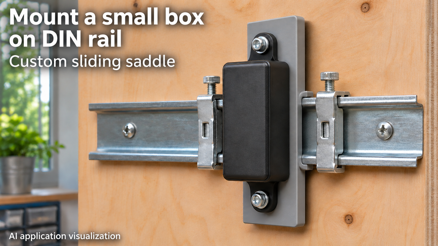
An existing DIN rail can provide an orderly mounting base for a lightweight hobby assembly. This saddle connects it to a small closed enclosure through two holes outside the rail. Fixed lower lips wrap around the rail edges. The illustration also shows two separate stops against lengthwise movement.
The saddle slides on from a free rail end. It has neither a snap latch nor an integrated longitudinal lock. Enclosure, metal rail, fasteners and stops are separate from the printed model. The AI application visualization does not establish a physical assembly test.
Measure width and rim thickness separately
rail_w means the full outside width of the matching rail. lip_t is the material thickness of the captured rims, not the overall height of the hat-shaped profile. Measure both on the actual part and check bend radii, rim width and clearance behind the rims.
At rail_w = 35 mm and fit = 0.4 mm, the internal width is 35.4 mm. With lip_t = 1.2 mm, the free rim slot is 1.6 mm high. fit is added once overall, not once on each side. A nominal 35 mm width alone does not establish compatibility with every rail sold under that size.
Allow space for the fixed retaining lips
Each lip has a fixed 3 mm inward projection. With a centred 35 mm rail and 0.4 mm total clearance, the calculated overlap is 2.8 mm per side; sideways movement reduces engagement on one side. The actual rim must accommodate this overlap without a lip hitting a bend or the mounting surface.
Check the 3 mm lip thickness itself and the entire sliding path from the free end to the final position. Rail fixings, neighbouring devices and existing end holders may block insertion. Do not force this part to snap on from the front.
Match the outer fixing holes to the enclosure
The default mounting plate measures 64.4 × 24 mm and is 3 mm thick. Two 3.4 mm through-holes are spaced 55 mm apart across the rail, outside the guide sidewalls. The uninstalled saddle is 7.6 mm deep overall.
mount_pitch must exceed the rail width including clearance and walls, plus the bore diameter, plus 2 mm. The model rejects combinations that are too narrow. Screw heads, washers, nuts and enclosure ears still need their own clearance; the bore diameter alone does not account for them.
Use suitable through-bolts and nuts or appropriate fixings for your own enclosure. Avoid overlong screws that contact the rail or backing board. Check access before sliding the assembly on. These two enclosure holes are not fixing holes for attaching the rail directly.
Install, restrain and check
Prepare the print on a side end face and inspect the lips, channel and bores in the slicer. Remove burrs and test the unloaded saddle first. Slide it to the chosen position, then restrain movement in both directions with suitable separate stops.
Limit this application to lightweight closed extra-low-voltage or hobby enclosures. Suitability for mains distribution, prescribed mounting systems or a particular load capacity has not been established. Check fit, fasteners and retention on your own assembly. Set all seven parameters around the actual rail and enclosure.
Next step