


Photography & workspace ·
Custom cold shoe mount: attach a small LED light to a desk base
Fit a lightweight accessory shoe to a wooden base with adjustable rails, countersunk fixing holes and a separate stop at the open end.
Give lightweight accessories a fixed place
A compact LED light on its own wooden base can be useful for small product photographs or a quiet desktop setup. This printed receiver guides the flat accessory foot beneath two side lips. A closed rear wall limits insertion, while the front remains open. The cold shoe is a passive mechanical fitting with no electrical contacts.
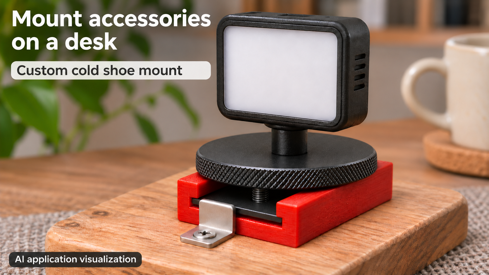
The image illustrates a possible assembly using a small light, the accessory’s locking disc and a separate metal stop in front of the foot. The light, fasteners, wooden base and stop are not part of the printed model. This AI visualization is not evidence of a physical fit or load test.
Measure the actual accessory foot first
Measure the flat plate’s width, usable insertion length and thickness. Also inspect the neck above the plate and the underside of the locking disc. Similar-looking flash and accessory shoes are not automatically interchangeable. The eight parameters allow adjustment without establishing universal compatibility.
shoe_w and shoe_l size the guide, while foot_t describes the foot thickness. fit is added once to the whole internal width and once to the free height, not once per side. A width of 18.6 mm, foot thickness of 2 mm and clearance of 0.3 mm produce an internal width of 18.9 mm and a free height of 2.3 mm.
Match the retaining lips to the locking disc
With overlap set to 1.8 mm, those defaults leave a 15.3 mm central opening for the accessory neck. A centred foot has a calculated overlap of 1.65 mm on each side; lateral movement reduces engagement on one side. Check both sideways limits before using the assembly.
A suitable locking disc sits on top of both lips and pulls the foot plate against them. It must not sit ineffectively between the rails on the foot plate. Thread length, disc diameter and lip height must work together. Tighten gently and check the printed part for distortion.
Install the countersunk fixings and secure the entrance
The default outer size is 24.9 × 27 × 8.3 mm. Two fixing holes lie on the centreline, 12 mm apart. With bolt_d = 3.4 mm and head_d = 6.4 mm, the calculated 90-degree countersink depth is 1.5 mm. Use matching screw heads that stay fully below the sliding surface.
Attach the empty receiver to a sufficiently large, stable base. Check screw length and the underside of the board. After inserting the accessory, secure the open entrance with a separate slide-out stop, such as the screwed metal angle shown. It must not lift the foot and must remain accessible for removal.
Print and check the stationary assembly
Inspect the lips and countersinks in the slicer. Placing the closed rear end on the build plate is one orientation to evaluate; decide on supports and adhesion from the layer preview. Remove burrs and first test the unloaded accessory foot.
Use only lightweight accessories on a quiet tabletop after checking fit and stability yourself. No camera load rating, overhead suitability or resistance to vibration has been established. A connected cable can also pull the base over. Set the eight model values around the parts you actually have.
Next step