


Hobby enclosures and covers ·
Keep a loosened screw attached to a lightweight hobby cover
The screw head slides inside a closed printed housing instead of falling out as a loose part. A smaller tool opening in the lid keeps the head captive inside.
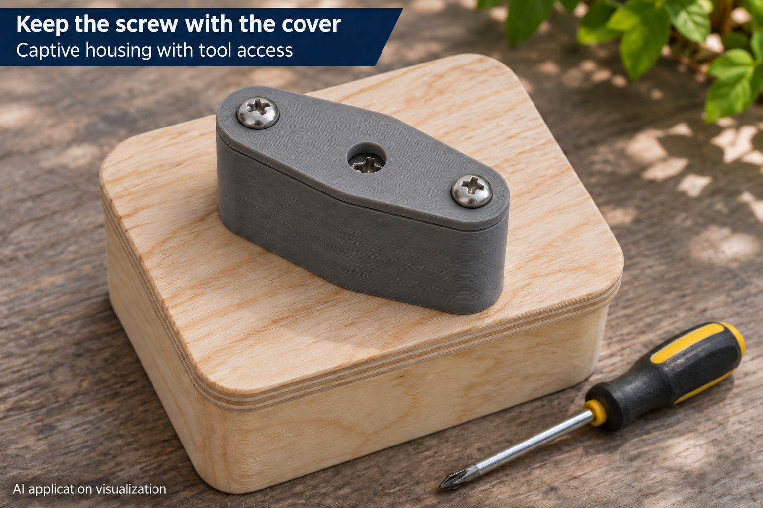
Keep the screw with the cover during opening
A lightweight hobby cover may need occasional removal. This printed housing can retain its screw head so the loosened screw does not become a separate item on the bench. Insert your screw into the open lower body before closing it; its shaft passes through the floor.
The lid has a smaller tool-access opening. The head stays inside underneath it but can move axially. Two additional screws at the side ends secure both lid and housing to your cover. The model includes neither a thread for the main screw nor a return spring.
Check the actual head and driver
Shaft clearance adjusts from 2.5 to 7 mm, initially 4.4 mm. Head clearance is 6–14 mm, initially 8.4 mm, while head height is 2–6 mm, initially 3.5 mm. Include the required printing allowance in these selected dimensions.
The tool opening is 3.5–10 mm, initially 5.5 mm. Your actual screw head must be larger than both the tool opening and floor passage while fitting freely in the cavity. The driver or bit must reach the drive recess through the opening. A large configured cavity alone cannot retain a screw head that is too small.
Plan withdrawal travel and screw length together
Additional axial withdrawal travel is 3–16 mm, initially 8 mm. Check that the screw can disengage fully from its mating part while staying in the housing. It is not automatically pulled back; its shaft must actually clear the mating part before the cover is lifted.
Wall thickness adjusts from 2 to 4 mm, initially 2.4 mm. Internal height is head height plus travel; floor and lid each use the wall thickness. Main screw length must account for the housing floor, cover thickness and required engagement in your separately provided mating part.
Fasten the lid and test movement
Side mounting holes are 2.5–5 mm, initially 3.4 mm. Their centre spacing is 18–40 mm, initially 24 mm. Keep enough spacing to prevent holes intersecting the head cavity. Print both parts with their flat outside faces on the bed.
Insert the main screw before the lid and choose mounting screws suitable for the total assembly height and cover. Then check driver access, free travel and retention when loosened. Intended only for lightweight hobby covers, without a safety function. The image is an AI application visualization; no physical test prints have been performed.
Next step