


Desktop camera modules ·
Aim a small tabletop camera board with a custom tilt mount
Four spacer bosses carry your camera PCB and a screw pivot sets its tilt. Measure the hole pattern, lens opening and cable clearance before creating the mount.
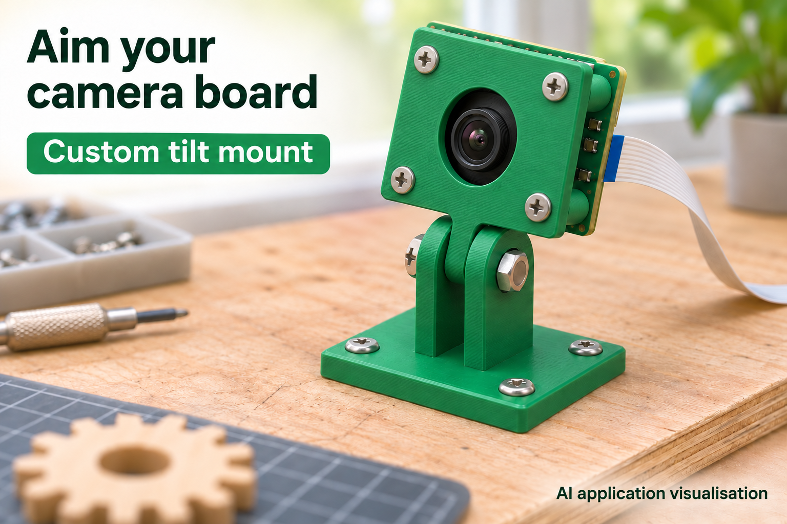
Aim a small camera at your work area
A camera board used on a hobby desk needs to point at a chosen area without being propped loosely against another object. This mount joins a PCB carrier to a screw-fastened base. The carrier’s central tab fits between two base cheeks. A separate M3 screw and nut form the tilt pivot and hold the selected position through friction.
The PCB sits behind the carrier on four spacer bosses. Its lens looks forward through a circular opening, while the back stays open for components and ribbon cable. This is a mount for your own small camera board, not an enclosed camera case or a universal attachment for finished cameras.
Measure hole centres rather than board edges
Measure horizontal and vertical centre-to-centre spacing of the four mounting holes. Horizontal spacing adjusts from 12 to 40 mm and vertical spacing from 10 to 35 mm; defaults are 21 and 12.5 mm. These values do not guarantee universal Raspberry Pi compatibility. PCB screw clearance adjusts from 1.8 to 3.5 mm. Check room for the actual screw heads and nuts around components as well.
Lens opening diameter adjusts from 6 to 24 mm. Its centre can move vertically from −6 to +6 mm relative to the hole-pattern centre. Measure the required clear diameter and actual lens position. The configurator limits collisions between the opening, frame edges and bosses, but cannot check the components on your particular board.
Allow space behind the frame and throughout tilting
Boss height adjusts from 2 to 10 mm, with a 4 mm default. It sets the separation between the PCB and carrier. Check that connectors, solder joints and the lens assembly fit within the available space. With a larger separation, also check that the frame opening does not shade the camera’s field of view. Inspecting the actual camera image is useful for this.
Base pivot height adjusts from 10 to 30 mm and wall thickness from 2.4 to 5 mm. No specific tilt-angle range is guaranteed. Check movement with the PCB, connector and cable fitted: nothing should strike the foot or desk. Route the ribbon without a sharp fold and leave enough slack so that it does not pull the camera away from its setting.
Print and assemble with your own hardware
The model creates two printed parts; camera and hardware are separate. Review orientation and any support needs in your slicer. Clear the holes and test assembly without force. Pivot and foot holes are fixed at 3.4 mm. Total lateral pivot clearance is 0.4 mm, not 0.4 mm on each side.
Fasten the board to the four bosses with suitable hardware without contacting traces or components. Place the carrier tab between the cheeks and fit the M3 screw and nut. Choose screw length for the actual joint stack and nut. Tighten only enough to hold the angle without distorting the printed cheeks or tab. Four mounting holes secure the base to your supporting surface.
For light tabletop cameras
After adjustment, check framing, cable pull and the security of the assembly. The mount is intended for light tabletop cameras, not overhead mounting. It has no detent or guaranteed holding-torque rating. An open carrier also does not protect electronics like a closed enclosure.
The image is an AI application visualisation. No physical test prints or compatibility tests with a specific camera module have been performed. After checking your own dimensions, create the STL or use the manufacturing option available on the model page.
Next step