


Breadboard projects ·
Mount a breadboard on a project plate without adhesive
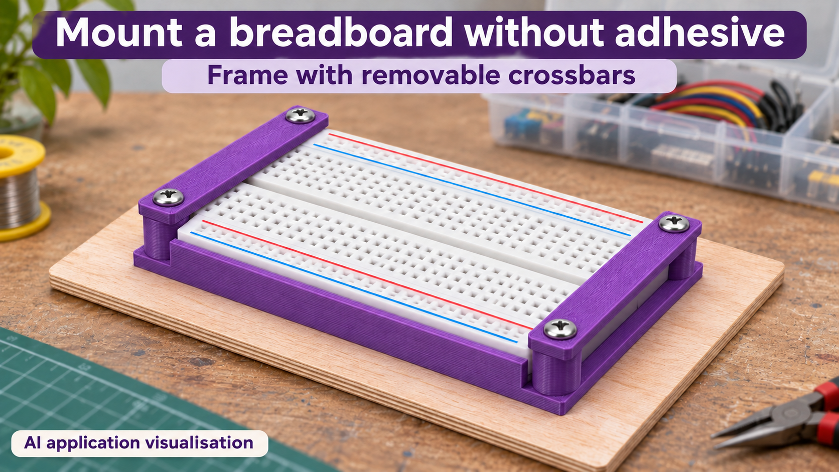
An open frame supports the breadboard’s bottom perimeter. Two removable crossbars retain its unused end margins while keeping the contact field accessible.
Remove the breadboard later without peeling adhesive
A breadboard on a learning or project plate should stay in place as leads are inserted. If you want to remove it later, a reversible mechanical mount is useful. This frame supports the outer bottom edge of your board. Two separately printed crossbars retain its free end margins and fasten through four support bosses.
The centre of the base remains open; this is not a closed electronics enclosure. The model consists of three printed pieces. Supply your own breadboard, screws and nuts. With suitable screw lengths, the same four fasteners can pass through your own carrier plate as well.
Measure the outside, including interlocking tabs
Measure the full length and width, including side connection tabs. Length adjusts from 35 to 170 mm and width from 25 to 85 mm. Height from the supported underside to the intended upper margin adjusts from 6 to 18 mm. The 85 × 56 × 10 mm defaults are a starting point, not a universal board specification.
The 0.2–1 mm fit allowance is added once to the overall length and once to the overall width. With a centred board it is shared between opposite sides. Measure the board completely rather than using extra allowance to compensate for overlooked protrusions.
Retain only unused end margins
Edge overlap adjusts from 1 to 4 mm. It affects the lower support opening and the reach of the crossbars at the ends. For a centred board, actual overlap onto its edge is the selected value minus half the total fit allowance. Check that your board still has enough supported margin.
The bars must not cover contact holes, side modules or intended plug connections. A board without suitable unused end margins is not automatically compatible. Do not simply increase overlap if it makes contact holes inaccessible. Also check that the actual underside profile sits securely on the open frame.
Print and assemble without distorting the board
Material thickness adjusts from 2.4 to 5 mm and screw clearance from 2.5 to 5 mm. The frame and two bars are laid out separately for printing. Clear the holes and support faces after printing. Insert the board, place the bars on the four bosses and fit the screws.
Select screw length for the base frame, boss height, crossbar and, where applicable, carrier plate and nut. Tighten evenly only enough to retain the board. The bars should not bend it. If the bars rest on the bosses but the board still rattles or is already being compressed, recheck board height and contact surfaces instead of tightening harder.
Check access before adding your circuit
Check access to every contact you intend to use and confirm that loosening the bars allows the board to be removed again. This frame is intended for low-voltage learning projects. It provides neither touch protection nor mains-voltage protection and adds no electrical function.
The image is an AI application visualisation of an installed but unpopulated breadboard. No physical test prints have been made. After checking dimensions and fit, create the STL for your own printer or use the available manufacturing option.
Next step