


Electronics ·
Mount a bar load cell on two end supports for a small DIY scale
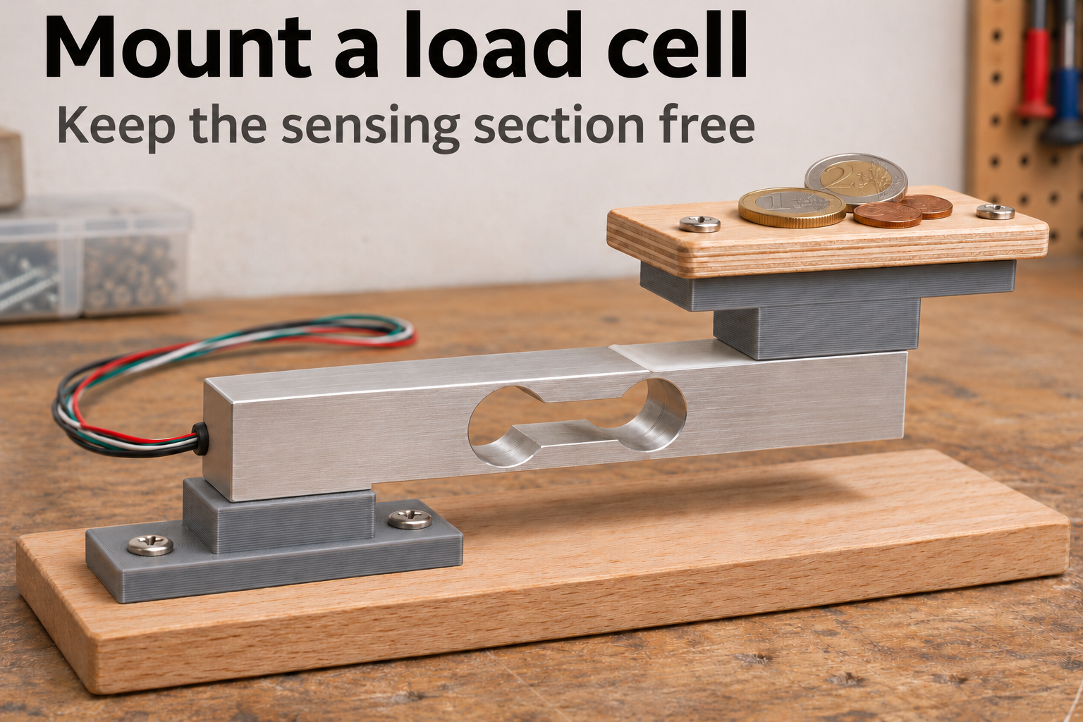
Two printed adapters connect a bar load cell to a base and weighing platform while leaving its central sensing section free to deflect.
Carry the load through opposite rigid ends
A small homemade tabletop scale needs its bar load cell attached at the intended rigid ends. This model creates two identical adapters, each with a wide base and a narrower raised contact pad. One adapter sits under the fixed beam end on the lower baseplate. The other is inverted above the opposite end and supports the weighing platform.
The resulting Z arrangement routes force through the baseplate, first pad, sensing beam, inverted second pad and upper platform. The central flexure must remain clear of the base, covers and screws. The load cell, readout electronics, two plates and fasteners are separate components. These printable supports do not constitute a complete scale.
Match the contact area and fasteners
Beam width can be set from 8 to 25 mm and the raised contact length from 16 to 40 mm. Match this pad to the rigid mounting end of your own cell; it must not extend into the active sensing area. Pad lift ranges from 3 to 14 mm, while the base thickness is adjustable from 3 to 7 mm.
The pair of cell fasteners can be spaced 8–28 mm apart, with clearance-hole diameters of 2.4–6.4 mm. The outer plate-mounting holes use 30–65 mm spacing and 2.4–5.4 mm diameters. These dimensions interact: contact length, screw heads and edge margins must leave adequate material. The model's geometric checks do not replace checking the actual cell drawing and hardware.
Assemble the adapters before attaching the plates
After printing, inspect pad flatness and check that the recessed head pockets beneath the broad bases suit your fasteners. Attach each adapter to its cell end first. Inner screw heads must sit within their pockets so they do not lift the adjoining baseplate or platform. Then fasten the outer holes to the lower and upper plates. Choose thread engagement and screw length for the specific load cell.
Route the signal cable in a slack loop so it neither pulls on nor props up the moving platform. Check clearance and zero reading without load, then use small known comparison masses. Calibration, overload stops and signal processing belong to the complete project. This application describes a light hobby scale, not a scale for people or trade measurements. No measurement accuracy, tested load rating or physical print validation is promised.
The image is an AI application visualization, not a photograph of a physically tested print. Accessories shown are not included in the STL.
Next step