


Camera and workspace ·
Mount an action camera on a tabletop tripod with a two-finger adapter
Position a small action camera for desk recordings. Two printed fingers connect a matching three-finger camera fitting to a separate metal tripod nut.
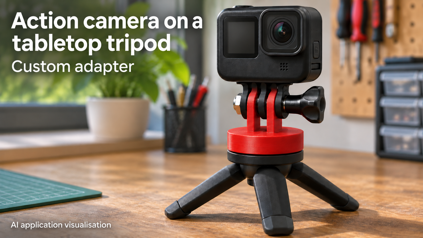
A camera connection for a desk setup
For a stationary desk recording setup, a small camera needs to sit on an existing tabletop tripod while allowing tilt adjustment. If its fitting has three matching fingers, this adapter provides the connection: two printed fingers interleave with them. A separate cross screw forms the pivot, and a hex nut inserted from below receives the tripod stud.
There is no printed thread. The camera, compatible three-finger fitting, cross screw and nut, tripod nut and tripod are separate items. The model name does not establish universal brand compatibility.
Measure both interfaces first
Measure the mating finger thicknesses and gaps, pivot bore and space for the screw head and nut. The two adapter fingers must enter the outer gaps without spreading them, while the centre camera finger needs clearance between the printed fingers. All five bores must align before inserting the cross screw.
On the tripod side, identify the thread and usable stud length. The default 6.7 mm clearance is intended around a separate 1/4-inch screw; it does not define a thread. Choose a matching metal nut, measure its width across flats and height, and check the actual thread fit.
Eight dimensions and the base thickness
Defaults are finger thickness 3 mm, clear gap 3.3 mm, pivot bore 5.3 mm, axis height 18 mm, base diameter 32 mm, nut width across flats 11.3 mm, nut height 5.5 mm and tripod clearance 6.7 mm. Axis height is measured from the base underside. Base thickness is nut height plus 3 mm, giving 8.5 mm and a 3 mm shoulder above the nut.
Ranges are finger thickness 2.5–5 mm, gap 2.5–6 mm, pivot bore 3.5–6.5 mm, axis height 14–28 mm, base 25–48 mm, nut flats 8–14 mm, nut height 3–8 mm and clearance 4–8 mm. Not every combination works: the geometry checks shoulder width, pivot clearance above the base and sufficient base area for the fingers.
Assemble and check the tilt
Print on the circular base and inspect the transverse bores and nut pocket. The hex pocket accepts the nut from below but does not automatically retain it against falling out. Secure the nut separately before transport. The base must sit flat on the tripod; the stud must neither bottom out nor engage too little thread.
Interleave the camera fitting, pass the cross screw through the aligned bores and tighten carefully. Do not force away a poor fit. Move the camera through the intended tilt range and check clearance to the base, screw and knob. On a secure surface, verify that the angle holds under the camera’s weight and that the tripod stays stable.
Limits of this application
Use is limited to a small camera on a tabletop tripod, not helmet, vehicle or overhead mounting. No load rating or vibration-resistant service has been established. Material, layer bonding, temperature and tightening pressure influence the joint.
The image is an AI application visualisation of the planned assembly. It does not document a physical print or load test.
Next step