


Adapters & connections STL guides ·
Custom Reducer STL: Measure Two Pipe Sizes for a Better Fit
Prepare the two connection sizes, engagement lengths and fit checks for a reducer STL you can print yourself. Learn why scaling a fixed download may not work.
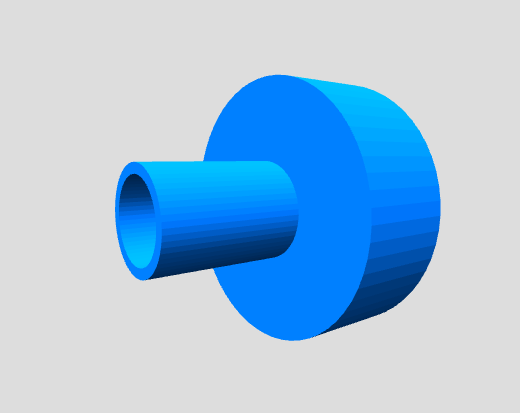
Two tubes can be only a few millimetres apart in size and still refuse to make a useful connection. A reducer STL is a way to model the transition between them. The important question is not simply whether the large end looks right: both mating surfaces, the engagement lengths and the space around the assembly need to work together.
This guide helps you prepare measurements for a custom reducer fitting. Start with the reducer fitting product page and compare its pictured geometry with the connection you need. Before purchasing a digital file, confirm that the available model controls and preview can represent both ends of your planned connection.
Seven controls for a reducer made to your dimensions
The configurator provides separate small-side and large-side inside diameters, wall thicknesses and straight section heights, plus the transition height. These controls let you match the two connections independently instead of scaling the complete part.
| Control | What to check |
|---|---|
| Small-side inside diameter | Measure the smaller mating surface and account for the fit you intend to test. |
| Small-side wall thickness | Check the material around the smaller bore and the resulting outside diameter. |
| Small-side height | Check the usable straight connection length against the adjoining component. |
| Large-side inside diameter | Measure the larger mating surface independently. |
| Large-side wall thickness | Check the larger outside envelope and room around neighbouring parts. |
| Large-side height | Check the straight connection length at the large end. |
| Transition height | Sets the length of the internal transition between the two bores. |
The outside has a step between the two sizes, while the internal passage tapers through the transition. Total height is the small-side height plus the large-side height plus the transition height. At each straight section, outside diameter equals inside diameter plus twice the wall thickness. Check both the internal fit and the complete outside envelope in the preview.
Measure each connection separately
Label your two components A and B. For each one, decide whether the printed fitting must slide over the outside or enter the opening. This determines which surface you should measure. A tube's outside diameter and bore are different measurements; substituting one for the other can produce a model that looks plausible but cannot assemble.
| Measurement to record | Why it matters |
|---|---|
| Outside diameter and bore of component A | Identifies the actual mating surface at the first end. |
| Outside diameter and bore of component B | Defines the second connection independently. |
| Available engagement length at each end | Reveals shoulders, ribs or surrounding parts that limit insertion. |
| Space between the components | Helps check whether the transition and its overall length can fit. |
| Desired fit and removal method | Distinguishes a loose locating fit from a connection intended to hold more firmly. |
Use this checklist alongside the seven model controls above. Keep both connection measurements separate and compare the preview with your notes. If your measurements are in inches, convert them when a field expects millimetres and confirm the imported scale again in your slicer.
Why scaling an existing reducer STL may not work
Uniform scaling changes the two ends by the same factor. If one end already fits and the other does not, scaling the complete mesh moves both away from their original dimensions. It also changes the length and wall thickness. A suitable parametric template should let you achieve the required combination through its available controls; inspect the result rather than assuming that every reducer template supports every connection.
Leave room for the printed fit
A measured tube diameter is a starting point, not a universal clearance value. Printer calibration, material and orientation can affect the finished opening. Use a short trial section or an initial prototype to check the relevant mating surfaces before committing to a longer print. Avoid adding a clearance twice if the selected model already has an allowance setting.
Check that the smaller passage remains open in the slicer's layer preview and that the transition leaves adequate material around both connections. A printable shape does not establish a pressure rating or fluid compatibility. Treat an untested fitting as a prototype for fit and space checks.
Choose the digital file for your own printer
When the template can represent your measurements, review the complete preview, selected configuration and current STL price before paying. A digital STL purchase gives you the mesh to slice and print yourself. Keep a record of the dimensions you entered: the STL contains the resulting geometry, rather than the original parametric editing history.
Start with the two parts you want to connect
Put both components on your workbench, label their mating surfaces and record the dimensions above. Then configure your reducer fitting STL and check whether it supports your required connection. The goal is a file that fits your project after a considered trial print, not another download whose dimensions you need to guess.
Next step