


Gears & mechanics STL guides ·
Crossed helical gear pair STL: Create a Custom-Size 3D Model
Create a custom-size crossed helical gear pair STL for your own 3D printer. Check the model controls, measure the fit and buy the generated digital file.
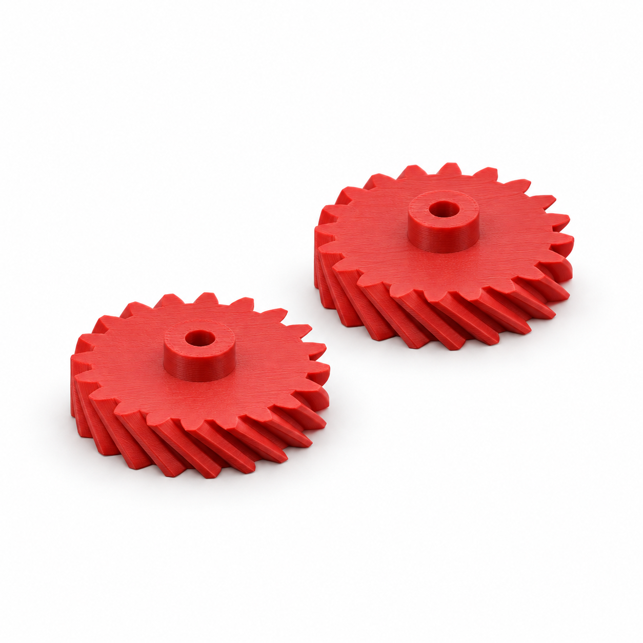
These equal crossed helical gears provide a 1:1 ratio between two offset shafts at 90 degrees. Both gears use the same hand of 45-degree helix. Unlike a bevel-gear pair, their shaft centre lines do not intersect. Face width and both bores adapt to a light manual assembly. The shortest distance between shaft centre lines is normal module × tooth count ÷ cos(45°), plus 0.2 mm assembly allowance. Default dimensions give approximately 42.63 mm. Align the middle planes of the toothed faces with the shortest line joining the axes.
With the Crossed helical gear pair for offset 90-degree shafts template, you can turn those measurements into a custom-size STL. Review controls such as normal gear module, teeth per gear, tooth-face width, check your model in the preview and choose the digital file. You buy the generated STL and print it on your own 3D printer, using your preferred filament and slicer settings.
Measurements for your crossed helical gear pair STL
The product page exposes the following useful geometry controls. Work from your measured parts and check the displayed units and the preview before entering final values.
| Model control | What to check |
|---|---|
| Normal gear module | Check this feature against the matching component and confirm its effect in the 3D preview. |
| Teeth per gear | Check this feature against the matching component and confirm its effect in the 3D preview. |
| Tooth-face width | Measure across the named feature and allow space for the neighbouring parts. |
| First-gear shaft bore | Measure the mating shaft or fastener and decide what type of fit the opening needs. |
| Second-gear shaft bore | Measure the mating shaft or fastener and decide what type of fit the opening needs. |
Check the mating mechanism before choosing an STL
A mechanism can look right in a picture and still fail to mesh or align. Keep the mating geometry, shaft connection and available axial space together in your notes. Changing a gear or drive component by uniform scaling also changes dimensions that may already be correct. Use the actual model controls and inspect a slow, unpowered trial assembly before considering a working mechanism.
Configure the model, buy the STL and print locally
- Open the crossed helical gear pair product page and compare the model preview with your application.
- Enter the relevant measurements. Use the units displayed beside each input; convert inch measurements before using a millimetre field.
- Review the complete geometry and keep a record of your parameter values. Check small openings, mating features and remaining wall thickness.
- Choose the digital STL purchase option and review the current price and order details before payment.
- After receiving the STL, open it in your slicer, confirm the imported dimensions and inspect the layer preview before printing.
Configure my crossed helical gear pair STL
Check a first print before making more
A CAD dimension and a printed dimension can differ. Print a fit sample or one prototype before making a batch, and check the features that contact other parts. Choose print orientation, supports and material for the actual geometry and application. There is no universal clearance or print profile that guarantees the fit on every machine.
Before you choose your STL
Why configure the model instead of scaling a download?
Uniform scaling changes all dimensions together. Here you can work with the available controls, including normal gear module, teeth per gear, tooth-face width, and check the result before purchase. Keep your input values for later revisions: the downloaded STL contains the final mesh, rather than the original parametric editing history.
What do I buy?
Select the digital STL option for the file you will print yourself. Review the current price and selected configuration before paying. Ordering a finished print is a separate option.
Make the next print fit your project
Have your measurements ready? Open the crossed helical gear pair template, adjust the model and inspect the preview. When the geometry matches what you need, choose your STL and take it to your own printer.
Next step