


3D Printing & Maker Projects ·
Custom U-Bracket STL: Configure a Made-to-Measure Mounting Part and 3D Print It
Need a U-profile in an uncommon size but do not want to model it from scratch? This practical guide explains how to set the width, height, length, wall thickness and hole rows online, download the STL and print the mounting part on your own 3D printer.
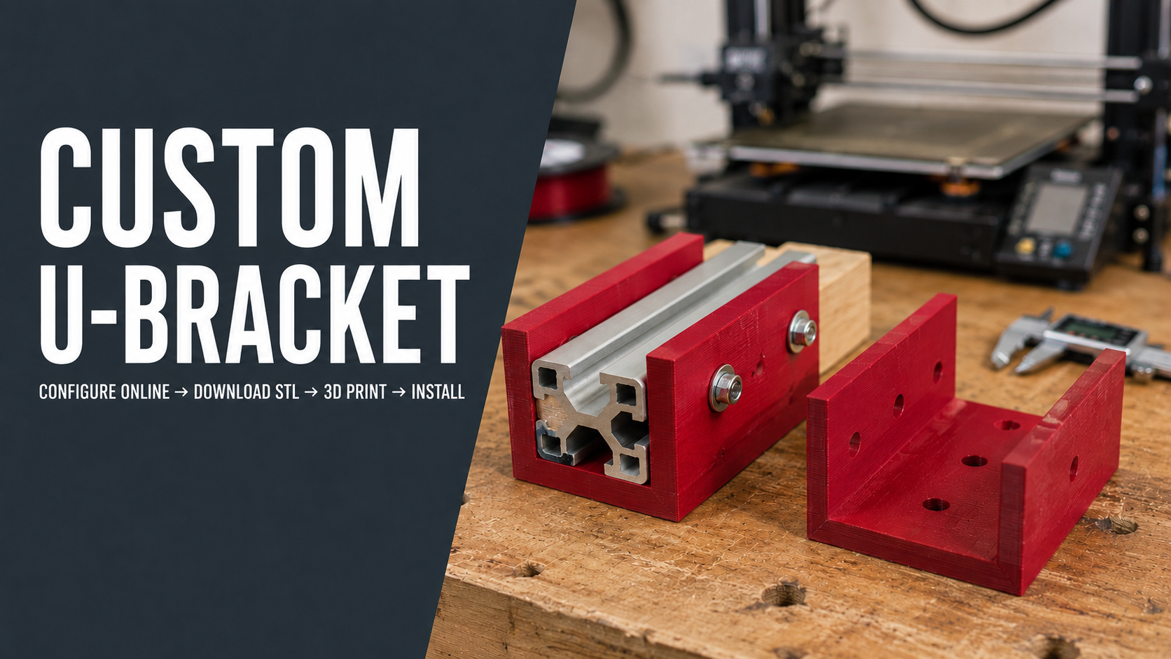
You have the printer—the missing part is the model
Anyone with a 3D printer knows the situation. You need a simple U-shaped bracket for an aluminium extrusion, wooden rail, small enclosure or workshop jig. The standard part is two millimetres too narrow, much longer than necessary or drilled in the wrong places. Printing the solution would be easy; creating the correct model is the actual obstacle.
This parametric configurator is designed for exactly that job. Enter the dimensions in your browser, inspect the generated U-profile in 3D and download the STL for Bambu Studio, OrcaSlicer, PrusaSlicer, Cura or another slicer. You get a model made for your installation without turning a small workshop fix into a complete CAD project.
What makers are really looking for: a usable STL that fits
Searches such as “custom U-bracket STL”, “3D printable U channel”, “custom mounting bracket for 3D printing” and “U-profile with screw holes” are rarely theoretical. Usually the calipers are already next to the project and the only missing piece is a printable file. A free model from an STL library is convenient when it happens to match. For a mounting part, however, a difference of only a few millimetres can make the download unusable.
Common goals in the 3D-printing community include:
- creating a made-to-measure U-profile as an STL,
- adjusting a bracket without learning CAD first,
- mounting a rail, extrusion or enclosure with a printed part,
- matching an existing row of screw holes,
- printing a fit-check before manufacturing a metal version,
- making a replacement or assembly aid on the same day.
A parametric model fills the gap between a fixed download and a new design from a blank screen. It handles the repeatable geometry, while you remain responsible for measuring, selecting a suitable fit and checking the finished part. That division of work is particularly useful for one-off repairs and workshop builds.
What exactly does the configurator create?
The model is a straight U-profile consisting of a flat base and two parallel side walls. Outer width, overall height, length and material thickness are adjustable. A centred row of round holes can be placed on the base, both sides, the left side, the right side, all three surfaces or nowhere.
Depending on the dimensions, the result can serve as a mounting shoe, guide, cover, spacer, short channel or holder for a rectangular component. It is not automatically a certified structural bracket. Suitability depends on the geometry, filament, layer orientation, fasteners, mounting surface and real load.
All eight parameters explained
| Parameter | What it controls | What to check |
|---|---|---|
| Outer Width | Total distance from the outside of the left wall to the outside of the right wall. | Subtract twice the material thickness to estimate the internal width. |
| Overall Height | Total height including the thickness of the base. | Check how far the walls may overlap the inserted component. |
| Length | Longitudinal dimension shared by the base and both side walls. | Consider available space, support area and print-bed size. |
| Material Thickness | Uniform thickness of the base and both walls. | Choose it for the application and verify the sliced toolpaths. |
| Holes per Surface | Number of holes on every enabled surface; zero creates none. | Leave useful material between the end of the part and the first hole. |
| Hole Spacing | Centre-to-centre distance between neighbouring holes along the length. | Measure from centres, not from the edges of the holes. |
| Hole Diameter | Diameter used for all generated holes. | Allow for the dimensional behaviour of your printer and filament. |
| Surfaces with Holes | Selects all, base, sides, left, right or none. | Only add holes where the screw and tool will remain accessible. |
Do not confuse outer width with the opening
The most important input is the outer width. It is not the clear space between the two walls. The theoretical internal width is:
Internal width = outer width − 2 × material thickness
For example, an outer width of 34 mm with 3 mm walls leaves a theoretical 28 mm opening. If the part around which the bracket fits is also 28 mm wide, that does not guarantee a sliding or press fit. Extrusion width, flow calibration, first-layer squish, filament shrinkage and print orientation all affect the real measurement.
For a new printer-and-material combination, I would print a short test section first. Ten or fifteen millimetres of length is often enough to test the opening and wall clearance. It costs little filament and prevents a long, otherwise perfect part from becoming scrap.
Planning holes that remain useful after printing
A hole row can look correct in the browser and still be awkward on the bench. Before downloading the STL, answer three practical questions: Is each hole in the required position? Is there enough material around it? Can a driver bit, nut or washer reach it after the bracket has been installed?
Measure hole spacing from centre to centre. When copying several existing holes, measure from the first to the last centre and divide by the number of gaps. This reduces the influence of a small measurement error. A digital caliper is useful, but an accurate steel rule can be sufficient for larger spacing.
FDM-printed holes often finish slightly undersized. You may need clearance in the configured diameter or carefully drill the opening after printing. There is no universal compensation value because printers, materials and profiles behave differently. A small hole-size calibration strip made on your own machine is more reliable than a generic number from the internet.
Choosing the right hole mode
Base only
Use base holes when the U-profile will be screwed to a panel, workbench, wall surface or enclosure while the inserted item remains unfastened from the sides.
Both sides
Side rows are useful when a rectangular extrusion, timber rail or housing must be secured laterally. Decide whether the design uses one through-bolt or separate screws from each side, and check access for the required hardware.
Left or right side
A single-sided row helps when the installation is close to a wall or another component blocks one face. It can also keep the visible side clean.
All surfaces
Holes on the base and both sides provide several mounting options. More holes do not automatically make a stronger assembly. Every opening removes material, and unused holes add no benefit.
No holes
A solid profile can work as a loose guide, protective channel, spacer or blank for later machining. Adhesive mounting may also be possible when it suits the materials and load.
Four realistic uses in a maker workshop
1. Mounting an aluminium extrusion
A short printed U-profile can locate a rectangular or construction extrusion on a base plate. Test the internal fit before printing the full length. If the extrusion is bolted through the sides, make sure the bolt head, washer and nut fit the selected geometry.
2. Holding a wooden rail
A timber strip can slide into the bracket as part of a jig, drawer guide or lightweight frame. Wood dimensions vary with manufacturing and moisture, so measure the actual piece in several positions rather than relying only on its nominal size.
3. Supporting a sensor or electronics enclosure
A compact box can sit between the two walls and be fixed through the base or sides. Remember to leave room for connectors, cable exits and the tool used to tighten the screws.
4. Prototyping a future metal part
Even when the final component will be machined or bent from aluminium or steel, a printed version is valuable. It can reveal collisions, inaccessible fasteners and incorrect hole positions before money is spent on the final part.
From calipers to STL: a practical workflow
- Photograph the installation. The image helps you remember nearby cables, edges and tool access.
- Measure the mating component. Record width, height and required engagement length at several points.
- Choose the type of fit. Decide whether the item should slide freely, be guided closely or be clamped.
- Calculate the outer width. Include the internal space, both walls and the tested clearance.
- Measure the hole pattern. Record diameter, quantity and centre spacing.
- Select the drilled surfaces. Enable only the rows that are accessible and useful.
- Configure the model online. Enter the values and regenerate the geometry.
- Rotate the 3D preview. Inspect the opening, hole positions, wall thickness and overall dimensions.
- Download the STL. Import it into your preferred slicer.
- Print a short test. Verify fit and hole diameter before committing to the final part.
- Print and install. Tighten fasteners carefully and monitor the part under its real operating conditions.
Slicer setup: the STL is only the starting point
The generated STL defines the geometry. Strength, accuracy and surface quality are created by the slicer settings and the printing process. PLA is convenient for fit checks and simple indoor parts. PETG is popular for tougher workshop components. ASA may suit some outdoor or warmer environments when printed correctly. These are general starting points, not universal approvals for a particular load.
Before starting the print, review:
- layer orientation in relation to the expected force,
- wall or perimeter count rather than relying only on high infill,
- first-layer quality and overall layer adhesion,
- support requirements for horizontal side holes,
- elephant-foot compensation where the fit is tight,
- a brim if tall narrow walls tend to warp or detach,
- the real printable area when the configured profile is long.
With the channel open at the top, the side walls can often be printed vertically without external supports. Round holes through those walls may show roughness at the upper arc. A calibrated bridge or overhang profile, a finer layer height or light post-processing may help. Do not rotate the entire part solely to improve one hole if that fills the full channel with support.
Why perimeters may matter more than excessive infill
Loads in a U-bracket often travel through the base, side walls and material surrounding the holes. Additional perimeters reinforce these regions more directly than a very dense interior. The appropriate number depends on nozzle diameter, configured wall thickness, filament and load.
Inspect the sliced preview layer by layer. Are the walls made from clean continuous paths? Is there solid material around every opening? Does the selected thickness produce awkward narrow gaps that the slicer fills inconsistently? The browser preview confirms the geometry; the slicer preview confirms how your machine intends to manufacture it.
Common mistakes that cause failed or unusable parts
- Mixing up internal and outer width: the specified outer width includes both side walls.
- Leaving no clearance: equal digital dimensions do not automatically create a real sliding fit.
- Measuring between hole edges: the configurator expects centre spacing.
- Forgetting the screw head: the hole fits, but the driver or washer collides with a wall.
- Adding unnecessary holes: extra openings remove material without improving the assembly.
- Choosing orientation only for appearance: layer direction should be considered with the applied forces.
- Printing the full length before testing: a short section would expose a fit error faster.
- Using an unsuitable filament near heat or outdoors: material must match the environment.
A note on functional mounting parts
A dimensionally correct STL is not a load rating. Do not use an unverified printed bracket for supporting people, fall protection, structural building work or another safety-critical function. For functional parts, assess the filament, print orientation, temperature, ageing, fasteners, mounting surface and consequences of failure.
FAQ about 3D-printing a custom U-bracket
Do I need CAD experience?
No CAD knowledge is required to change the offered parameters. You still need to measure the installation, plan the fit and verify the generated model.
Can I use the STL with Bambu Studio, Cura or PrusaSlicer?
Yes. The generated STL is intended as input for common slicers. Whether the chosen length fits your build plate depends on the printer.
How do I calculate the internal width?
Subtract twice the material thickness from the outer width, then add the clearance that you have tested on your own printer.
Can I create holes only in the base?
Yes. Other modes include both sides, left only, right only, all three surfaces and no holes.
Can the base and side holes have different diameters?
The configurator uses one shared hole diameter across all enabled surfaces. Different sizes require later CAD editing or careful mechanical post-processing.
What happens when holes per surface is set to zero?
No hole row is created. You can also select the mode with no drilled surfaces.
Which filament should I choose?
PLA is often practical for prototypes, PETG for many workshop parts and ASA for suitable outdoor or warmer applications. The final choice depends on load, temperature, UV exposure and required lifetime.
Should I make a test print?
Yes, especially for close fits and copied hole patterns. A short test section quickly reveals the dimensional behaviour of your printer and filament.
Conclusion: a simple part where the right dimensions matter
A U-bracket is simple in principle, but useful only when the opening, length and hole rows match the real installation. A browser-based configurator provides a direct workflow: measure the project, enter the values, inspect the preview, download the STL and manufacture the result on your own printer.
For the 3D-printing community, this is a practical shortcut for custom dimensions, repairs and one-off workshop builds. You avoid modelling the complete part from scratch while retaining control over material, orientation and slicing. My most useful recommendation is straightforward: when the fit matters, print a short sample first and the full component second.
Create your custom U-bracket STL
Set the outer width, height, length, wall thickness, hole count, spacing, diameter and drilled surfaces. Inspect the result in your browser, then prepare it for your own 3D printer.
Nächster Schritt