

Mounting Brackets & Hardware ·
Custom Mounting Bracket: Configure Dimensions, Hole Patterns and Reinforcement Ribs
Need a mounting bracket that standard hardware cannot provide? Learn how to configure the width, height, projection, material thickness, hole pattern and reinforcement ribs of a custom 90-degree bracket, then download the STL or order a 3D print.
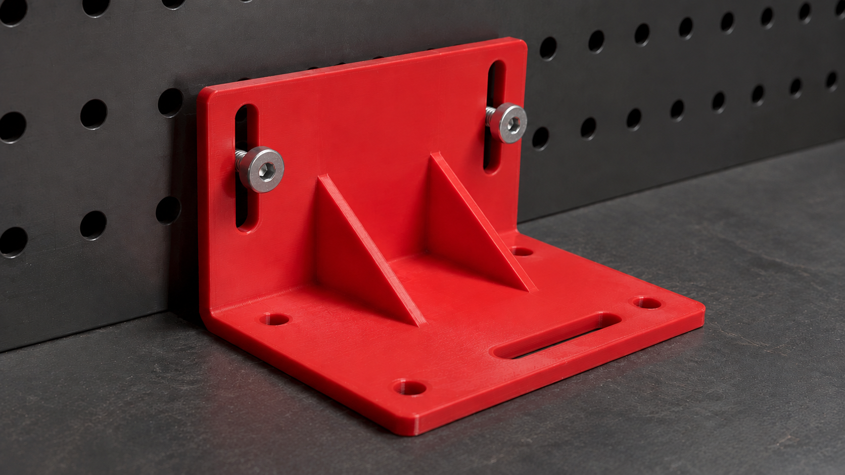
When a standard mounting bracket does not fit
Off-the-shelf brackets work when their dimensions and mounting holes match your project. In machinery, workshop fixtures, enclosures, prototypes and repair projects, however, even a few millimetres can make the difference between a clean installation and a bracket that cannot be used. A custom mounting bracket lets you define the most important dimensions and fastening options directly in your browser.
What people search for when standard brackets do not fit
Searches such as “custom mounting bracket” or “L bracket with slotted holes” usually come from a specific installation problem: the bracket is too short, the horizontal support is too shallow, the mounting surface is restricted or the available holes do not align with the mating part.
- custom mounting bracket
- custom L bracket
- mounting bracket made to measure
- 90 degree mounting bracket
- L bracket with holes
- mounting bracket with slotted holes
- reinforced angle bracket
- custom wall bracket
- 3D printed mounting bracket
- mounting bracket STL generator
A parametric model avoids redesigning the complete part for every new size. Enter the required dimensions, select the hole pattern and inspect the generated geometry in the 3D preview.
Which mounting bracket parameters can be configured?
| Parameter | Function | What to check |
|---|---|---|
| Width | Defines the overall width of the bracket in the X direction. | Available space, support area and spacing between fastening points. |
| Height | Defines the height of the vertical mounting face. | Usable wall area and access for screws and tools. |
| Depth / Projection | Defines how far the horizontal support projects from the wall. | Required support depth and the resulting lever arm. |
| Material Thickness | Controls the thickness of the bracket geometry. | Available space and automatically derived screw and hole dimensions. |
| Hole Pattern | Selects compact, universal, heavy or slots. | Choose according to the screws, mating part and required adjustability. |
| Reinforcement | Adds automatically positioned triangular ribs. | Check side clearance, screw access and possible collisions. |
Width: How much support area is required?
The width determines how far the bracket extends sideways. A wider bracket provides more room for mounting holes and can distribute forces across a larger area. It also consumes more installation space and printing material.
Measure the usable width at the installation location. Account for edges, nearby components, cables, covers, screw heads and assembly tools. If the bracket must fit between two fixed surfaces, include suitable installation clearance.
How to determine the bracket height
The height controls the size of the vertical mounting face. A taller face can accommodate additional or more widely spaced fastening points, but only if sufficient wall or panel area is available.
- Measure the usable vertical mounting space.
- Locate existing holes, slots or profile grooves.
- Confirm that every screw can be reached with a tool.
- Check for enclosure edges, cables and covers.
- Verify access for nuts or backing plates.
Depth and projection: Consider the lever arm
The depth determines how far the horizontal support projects from the vertical surface. It must support the intended component, but increasing the projection can also increase the lever arm and the forces acting on the bracket, fasteners and mounting surface.
Use only the projection required for installation. Off-centre loads, vibration or changing forces require additional technical evaluation. A bracket that fits geometrically is not automatically suitable for every load case.
Understanding material thickness
Material thickness affects geometry, installation space and material consumption. The configurator derives screw and hole diameters from the selected thickness. Compare the generated dimensions with the actual screws, washers and required clearances.
- Check screw-head and washer contact area.
- Keep nuts and tools accessible.
- Compare hole diameter with the intended fastener.
- Ensure enough material remains around each opening.
- Confirm that the thickness fits the available space.
Which hole pattern should you choose?
Compact
The compact pattern is intended for smaller brackets and simple fastening situations with limited mounting area.
Universal
The universal pattern provides multiple fastening options and is useful when the final screw positions are not yet fixed.
Heavy
“Heavy” is the name of a hole-pattern geometry. Selecting it does not provide a certified load rating or guarantee heavy-duty suitability. Capacity depends on dimensions, material, manufacturing, print orientation, fasteners, mounting surface and the complete load case.
Slots
The slots option creates elongated adjustment holes, allowing the bracket or attached component to move into position before final tightening.
When are slotted mounting holes useful?
- Adjust a component horizontally or vertically
- Compensate for small measurement differences
- Set the distance from an edge
- Fine-tune a sensor or switch position
- Move a mounting plate before final tightening
Slots reduce the amount of material around the fastener. Ensure the screw head or washer properly covers the opening and that the connection suits the actual forces.
What do the reinforcement ribs do?
When reinforcement is enabled, triangular ribs are placed between the vertical and horizontal faces. They can support the corner geometry and influence stiffness, but require additional side clearance.
- Check for collisions with the mounted component.
- Keep screws and tools accessible.
- Allow clearance for cables and enclosure parts.
- Review the intended print orientation.
- Confirm the bracket can still be inserted into position.
Typical applications
- Mounting enclosures and covers
- Holding sensors, switches or control devices
- Workshop fixtures and test setups
- Prototypes and functional mock-ups
- Equipment platforms and spacer brackets
- Mounting plates inside cabinets
- Laboratory, model-making and DIY projects
- Checking dimensions before manufacturing a metal bracket
3D-printed bracket, prototype or final component?
A 3D-printed mounting bracket can be used as a fit-check model, drilling template, assembly aid or prototype. After appropriate technical assessment, it may also be suitable as a functional component. It must not automatically be considered equivalent to a steel or aluminium bracket.
Evaluate static and dynamic loads, lever arm, vibration, temperature, UV exposure, moisture, printing material, layer adhesion, print orientation, fasteners, mounting surface and the consequences of failure.
Important safety notice
Do not use an untested 3D-printed bracket for supporting people, fall protection, structural building elements or applications where failure could cause injury or substantial damage. Safety-critical and highly loaded installations require appropriately engineered and tested components.
How to configure your custom mounting bracket
- Measure the installation space and mating components.
- Define the required width.
- Measure the usable vertical height.
- Determine the required projection.
- Select the material thickness.
- Choose compact, universal, heavy or slots.
- Enable reinforcement if sufficient clearance is available.
- Inspect the preview for collisions and fastener access.
- Compare generated hole sizes with the actual screws.
- Produce a test part if fit or tolerances are uncertain.
- Test installation and loading under controlled conditions.
Download the STL or order a 3D print
After configuration, inspect the generated model in the 3D preview. Download the STL for your preferred slicer or continue with the order process to have the bracket 3D printed. Before manufacturing, verify all dimensions, hole sizes, clearances and fastening positions against the real installation.
FAQ about custom mounting brackets
What is the difference between width, height and projection?
Width runs sideways, height defines the vertical mounting face and projection defines the depth of the horizontal support.
Can I create a bracket with slotted holes?
Yes. Select “slots” to create elongated holes for adjustable positioning.
What does the “heavy” hole pattern mean?
It is a geometry option, not a guarantee of a particular load capacity.
What happens when reinforcement is enabled?
Triangular ribs are placed between the vertical and horizontal faces.
Are hole diameters generated automatically?
Yes. Always compare them with the fasteners you intend to use.
Can I download the bracket as an STL?
Yes. The model can be downloaded as an STL or ordered as a 3D print.
Can it be used as a heavy-duty bracket?
That requires an assessment of the complete load case, material, print orientation, fasteners and mounting surface.
Conclusion
A custom mounting bracket is useful when standard dimensions and fixed hole patterns do not match the installation. Width, height, projection, thickness, hole pattern and reinforcement can be adjusted to fit the available space. Parametric configuration does not replace load calculations or safety assessment, but it provides a fast route from custom measurements to a printable model.
Configure your custom mounting bracket
Set the dimensions, hole pattern and reinforcement, then inspect your individual 90-degree bracket in the 3D preview.
Nächster Schritt