


Gears & Linear Drives ·
Custom Gear Rack: Configure Module, Length and Size for a Linear Drive
Need a gear rack that standard parts cannot provide? Learn how to configure shape, length, gear module, width and height, match the correct pinion and generate an STL or order a 3D print.
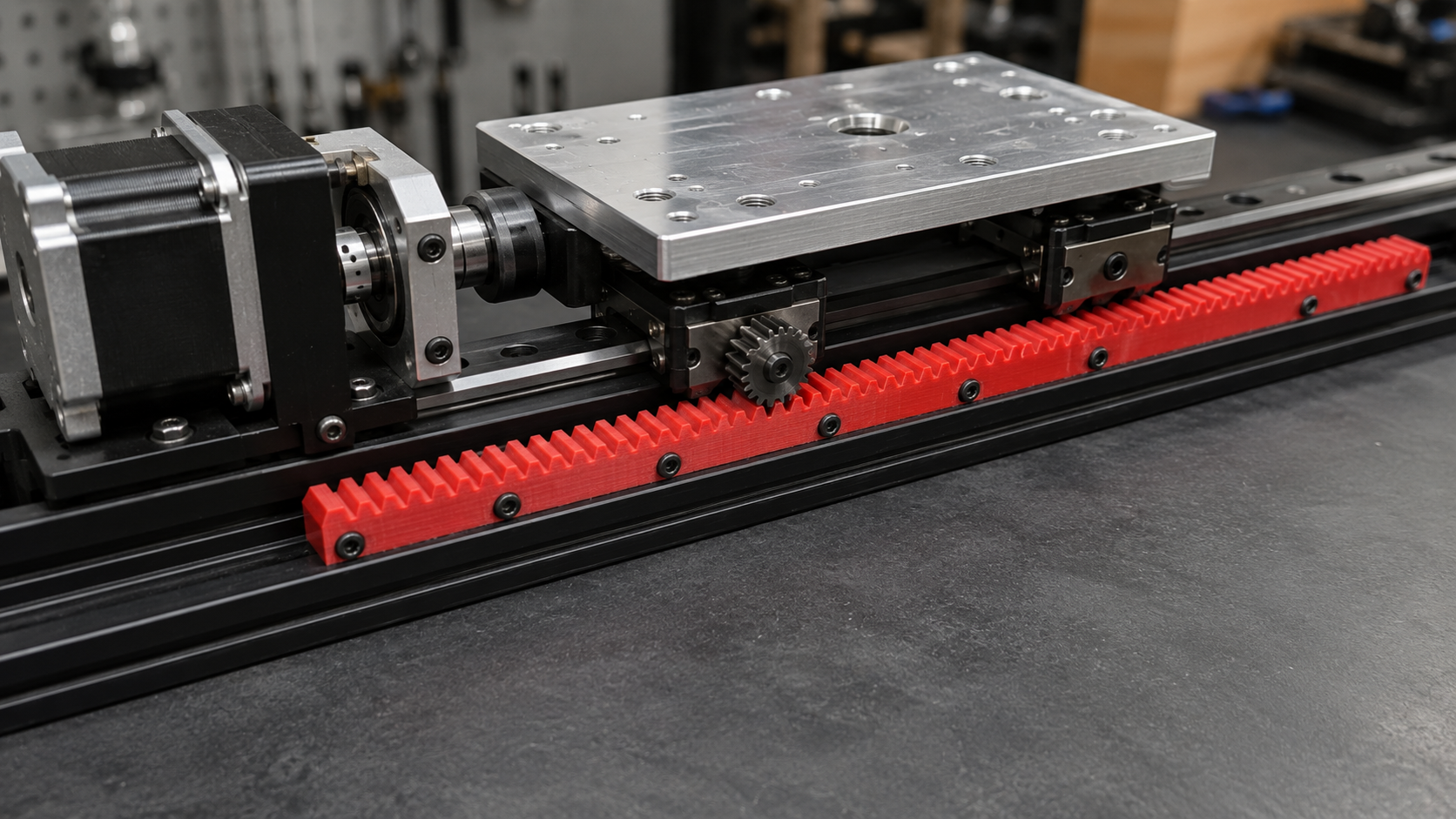
When a gear rack must fit the available space
A custom gear rack is useful when a motor or handwheel must create straight-line movement but standard lengths and cross-sections do not suit the mechanism. Typical projects include sliders, adjustments, model axes, camera rigs, robotics, fixtures and prototypes. A suitable length is only part of the specification: the rack module must match the pinion that engages it.
What is the search intent behind “3D printed gear rack”?
Users normally want to solve a specific motion problem. They may need a rack for an existing pinion, a non-standard length or a quick way to prototype a rack-and-pinion linear drive without building the tooth geometry manually in CAD.
- custom gear rack
- 3D printed gear rack
- gear rack STL generator
- module 1 gear rack
- rack and pinion mechanism
- DIY rack and pinion linear actuator
- convert rotary motion to linear motion
- gear rack calculator
- gear rack for stepper motor
- plastic replacement gear rack
The intent combines technical research with an immediate action: understand the module and dimensions, configure the model, inspect the preview and obtain an STL or printed part.
How does a rack-and-pinion drive work?
A gear rack can be understood as a straight, unrolled gear. A rotating pinion engages the teeth and moves either the rack or the pinion carriage along a linear axis. The mechanism can also work in reverse, turning linear movement into rotation.
Unlike a lead screw, a rack-and-pinion mechanism does not have a self-locking thread. It can suit longer travel, visible demonstrators and mechanisms where a pinion should act directly on a straight tooth row. The guide, bearings and drive must be designed as one complete system.
Which parameters can be configured?
| Parameter | Function | What to check |
|---|---|---|
| Shape | Selects the available base shape, such as standard or round. | Inspect the preview and choose the contour that fits the intended mounting method. |
| Length | Defines the overall rack length. | Travel, end positions, mounting space and printer bed size. |
| Gear Module | Controls the size and pitch of the teeth. | Must match the module of the pinion. |
| Width | Defines the axial tooth width and overall part width. | Compare with pinion face width, side guides and available space. |
| Height | Defines the rack body below the teeth. | Mounting surface, stiffness and distance to the linear guide. |
The gear module must match the pinion
The metric module m defines tooth size. A rack and pinion can only mesh correctly when they use the same module. A module 1 pinion will not properly engage a module 1.5 rack, even if the parts appear similar.
For a metric spur pinion, the pitch diameter is:
Pitch diameter d = module m × number of teeth z
The linear tooth pitch along the rack is:
Tooth pitch p = π × m
With module 1, the distance between corresponding points on adjacent teeth is approximately 3.14 mm. This relationship can help identify an existing rack, but a replacement part may also require a matching pressure angle, tooth profile and backlash.
How far does the rack travel per pinion revolution?
With ideal engagement and no slip, one complete pinion revolution moves the rack by the circumference of the pinion pitch circle:
Linear travel per revolution s = π × m × z
A module 1 pinion with 20 teeth therefore produces a theoretical travel of approximately 62.83 mm per revolution. In a real mechanism, backlash, elastic deformation, alignment and manufacturing tolerances affect actual positioning accuracy.
This relationship is particularly useful when selecting a rack for a stepper motor, geared motor or handwheel. Motor speed, gear reduction and pinion tooth count jointly determine linear speed.
Length: required travel is not always total rack length
Do not automatically set rack length equal to the desired travel. Additional teeth may be required to keep the pinion fully engaged at both end positions. Mechanical stops, mounting areas and safety clearances also consume length.
Before configuring the model, check:
- What is the required usable travel?
- Where is the pinion at both end positions?
- Will enough teeth remain fully engaged?
- Does the mechanism need physical end stops?
- How will the rack be supported and mounted?
- Does the rack fit the printer bed, or would segmentation be required?
Match rack width to pinion face width
Width describes the tooth dimension across the direction of travel. It should be coordinated with the usable face width of the pinion and the available installation space. A narrow pinion on a wide rack uses only part of the available tooth face. An excessively wide pinion may overhang or collide with brackets.
More width does not automatically guarantee higher force capacity. Module, material, tooth-root geometry, print quality, bearing arrangement, alignment, torque and duty cycle also matter.
Choosing the rack body height
Height determines how much material remains below the teeth. A low body saves space but can flex more easily or offer less room for mounting. A taller body consumes more space and material.
Consider:
- the distance between the pitch line and linear guide,
- mounting screws, clamps or brackets,
- bending across unsupported sections,
- collisions with the carriage, motor mount and limit switches,
- print orientation and contact area on the build plate.
What does the shape setting control?
The configurator provides base-shape options such as standard and round. Because the exact body is generated from the entered values, use the 3D preview to evaluate which contour fits the intended support, guide or mounting arrangement.
Shape does not change the main compatibility rule: the pinion still needs the same module and a compatible tooth profile.
Real application: a motorized sliding axis
Imagine a small platform moving along a linear guide. A stepper motor is mounted on the carriage and drives a pinion. The rack is fixed parallel to the guide on the machine frame.
| Planning point | Example decision | Reason |
|---|---|---|
| Module | Identical to the existing pinion | Provides geometrically compatible engagement. |
| Length | Usable travel plus engagement reserve | Keeps the pinion engaged at both ends. |
| Width | Matched to the pinion face | Avoids unnecessary overhang and collisions. |
| Height | Matched to the bracket and centre distance | Positions the rack tooth line correctly. |
| Guidance | Separate linear rail | The rack provides drive, while the rail controls the carriage. |
| Clearance | Verified during test assembly | Prevents binding while limiting lost motion. |
In this arrangement, the rack provides feed movement. The linear rail controls the carriage path, while the motor mount and bearings keep the pinion at the correct engagement depth.
Typical applications for a 3D-printed gear rack
- Linear axes for prototypes and demonstrators
- Sliding doors, flaps and locking mechanisms
- Camera or sensor positioning
- Robotics, model making and educational projects
- Motorized height or length adjustment
- Dosing and positioning mechanisms
- Replacement for a broken plastic rack
- Fit testing before metal or production manufacture
Gear rack for a stepper motor: What else is required?
A rack does not connect directly to a motor. The mechanism needs a compatible pinion, shaft connection, rigid motor mount and guide for the moving component. Limit switches, a reference sensor, gearbox and controller may also be required.
Motion calculations should include motor steps, microstepping, transmission ratio and travel per pinion revolution. Mechanical backlash can cause positioning error when direction changes. Software compensation cannot correct a misaligned or binding mechanism.
Setting pinion engagement in practice
The pinion should neither be forced too deeply into the rack nor contact only at the tooth tips. An overly tight centre distance causes friction and binding, while too much separation increases backlash and can allow tooth skipping.
An adjustable motor mount or slots can help set engagement. After assembly, rotate the pinion by hand across the complete rack and verify that resistance remains even. A straight mounting surface and a rack aligned parallel to the linear guide are essential.
Segmented racks for longer travel
If the required length exceeds the printer bed, multiple segments may be necessary. The transition is demanding: tooth pitch must continue correctly across the joint, and the segments must not be laterally offset or twisted.
The configurator generates a rack with a defined length; it does not automatically guarantee a pitch-correct segment connector. For segmented assemblies, use an alignment fixture or a mating pinion to check tooth spacing across each joint.
3D printing: orientation and tooth quality
A rack can often be printed flat with its body on the build plate. This provides a stable base and may avoid major support structures. The best orientation still depends on geometry, load direction, material and printer.
Inspect:
- clean tooth tips without excessive over-extrusion,
- uniform tooth spacing across the complete length,
- a straight body without warping,
- sufficient perimeters below the tooth roots,
- a controlled first layer without excessive elephant foot,
- dimensional accuracy of height and width.
Material choice and wear
PLA can be suitable for fit checks, educational models and lightly loaded mechanisms. PETG may provide more toughness in some designs, while other materials can offer advantages for heat, friction or outdoor exposure. Material name alone does not determine service life.
Contact pressure, torque, speed, lubrication, contamination, alignment, temperature and the pinion/rack material pairing all influence wear. A steel pinion may wear a printed rack differently from a matched plastic pair.
Important safety notice
Do not use an untested 3D-printed rack for lifting people, fall protection or applications where tooth failure or skipping could cause injury. High forces, continuous duty and safety-critical machinery require professional design and testing of the complete drive system.
How to configure your custom gear rack
- Identify the intended pinion and its module.
- Define the required usable linear travel.
- Add length for end positions and full engagement.
- Select the shape that suits the mounting method.
- Match width to the pinion and available space.
- Choose height according to the body, guide and centre distance.
- Inspect proportions and possible collisions in the 3D preview.
- Download the STL or order the 3D print.
- Produce a short test or trial assembly first.
- Check alignment, backlash and free movement over the full length.
FAQ about custom gear racks
What is a gear rack?
It is a straight machine element with a row of teeth. Together with a pinion, it converts rotary motion into linear motion or vice versa.
Which pinion fits the rack?
The pinion must have the same module and a compatible tooth profile. Pinion face width and the intended engagement depth must also suit the design.
How is rack tooth pitch calculated?
For a metric module, p = π × m. With module 1, the pitch is approximately 3.14 mm.
How far does the rack move per revolution?
The simplified relationship is s = π × m × z of the pinion. Real backlash and deformation can affect positioning accuracy.
Can I use the rack with a stepper motor?
Yes, together with a suitable pinion, shaft connection, motor mount, bearings, linear guide and controller.
Can a long rack be assembled from sections?
Yes, but tooth pitch, alignment and height must continue accurately across every joint. An alignment fixture is normally useful.
Can I download the rack as an STL?
Yes. After configuration, the model can be downloaded as an STL or ordered as a finished 3D print.
Is a printed rack suitable for high force?
This cannot be determined from dimensions alone. Material, printing, pinion, bearings, speed, load case and safety requirements must be evaluated.
Conclusion
A custom gear rack is useful when standard length, cross-section or body shape does not fit the mechanism. Module is the most important compatibility value: rack and pinion must match. Length, width and height are then adapted to travel, installation space, guidance and mounting.
Online configuration speeds up model creation but does not replace load, wear or machine-safety calculations. For prototypes, replacement parts and appropriately evaluated applications, it offers a direct route from dimensions to an STL or printed component.
Configure a custom gear rack
Select the shape, length, gear module, width and height, then inspect your rack directly in the 3D preview.
Nächster Schritt