Measure spare parts correctly: The 10-minute checklist (damit’s beim ersten Druck passt)
You want a spare part without CAD or customize - but the part should fit at first try? Then measuring is the decisive step. In this checklist, I'll show you which dimensions are really important and how to avoid typical mistakes and which tolerances you should plan for in 3D printing.
- 10-minute quick start (if you are in a hurry)
- Werkzeug & Vorreadyung
- The measurement checklist: 6 values that are almost always enough
- Measure hole spacing correctly (center-to-center)
- tolerances & fits (Schraube/Steck/Klemm)
- The 7 most common measurement errors
- Nächster Schritt: template wählen & configure
- FAQ
10-minute quick start (if you are in a hurry)
- Outer dimension (W/H/L) + Construction space measure
- Inner dimension/opening measure (if something has to go in/over something)
- hole-Ø measure (screw/bolt)
- holeabstand Mitte-Mitte measure (crucial!)
- Wandstärke/materialstärke determine
- Tolerance add (usually +0.2 to +0.6 mm)
After that: Open category →, select a suitable template, enter the parameters - done.
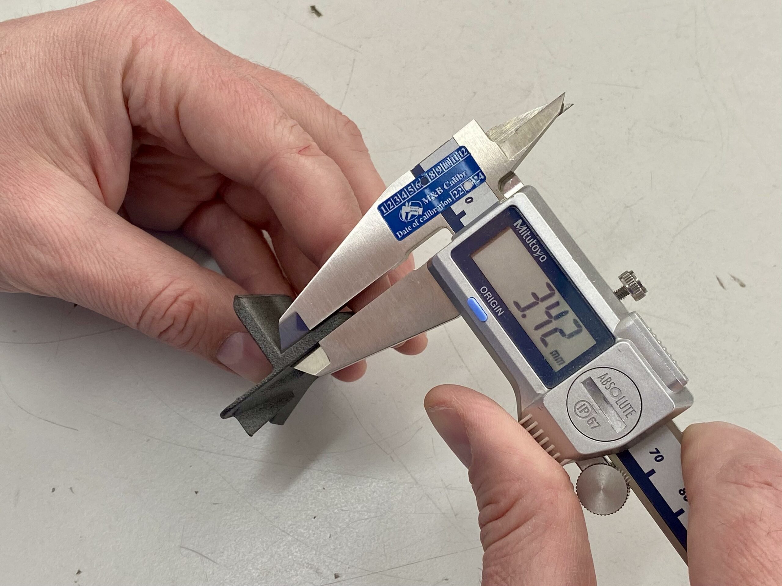
Werkzeug & Vorreadyung
Ideal is a digital caliper. This allows you to measure external and internal dimensions and depths very quickly. Purely for understanding: Ruler/caliper also works - but the error rate increases.
- ✅ Caliper (0.1 mm is enough, 0.01 mm is luxury)
- ✅ Stift/Notiz or Handy-Notiz
- ✅ ggf. angle/Anschlag (für gerade Ausrichtung)
Tip: If the original part is broken, measure - if possible - at the Counterpart (e.g. on the housing, on the bore, on the counterpart). This is often more reliable.
The measurement checklist: 6 values that are almost always sufficient
For many spare parts such as brackets, adapters, spacers, covers and mounting plates, these 6 values are sufficient. Measure twice if possible and note the numbers directly.
| Measured value | Why wichtig? | Praxis-Tip |
|---|---|---|
| Outer dimensions (W/H/L) | Passt das part in den verfügbaren Bauraum? | Always measure the narrowest area (not just "approximately"). |
| Inner dimension / opening | Wenn das part über etwas drüber muss or etwas aufnehmen soll. | Innenmaße brauchen meist etwas more Spiel (siehe tolerances). |
| hole-diameter | Schraube/Bolzen muss yourch or greifen. | Yourchgangsloch meist größer als Schraube (z. B. M4 → 4,2–4,6 mm). |
| holeabstand (Mitte-Mitte) | Dawith vorhandene boreen exakt getroffen werden. | Never measure edge-to-edge - always center-to-center. |
| Wandstärke / materialstärke | Bestimmt Stabilität, Schraubenhalt and Klemmkraft. | If under load: preferably 1-2 levels thicker. |
| Radii / Chamfers | Prevent collisions, facilitate assembly. | Wenn unclear: lieber smalle Fase statt scharfer Kante. |
Measure the hole spacing correctly (center-to-center)
This is the most common reason why a part "almost" fits: the hole spacing is slightly off. Therefore measure Center-to-Center. Two simple methods:
- Directly: Messschieber-Spitzen in die holewithten (wenn gut möglich).
- Trick: Außenkante-zu-Außenkante messen and dann hole-Ø deduct:
Mitte-Mitte = (Außen-Außen) − hole-Ø
Tip: If you get two measurements (e.g. 39.8 mm and 40.1 mm), take the average value or measure again with a firmer stop. If in doubt print a small test plate than "at random".
Tolerances & fits (screw / plug / clamp)
3D Printing is not a "zero game". Allow for tolerance to keep parts mountable. These guide values work as a starting point for many applications:
| application | Game (approximate value) | Example |
|---|---|---|
| Schraube als Yourchgang | +0.2 to +0.6 mm | M4 → 4.2-4.6 mm |
| Push/Push fit | +0.3 to +0.8 mm | 10 mm spigot → holder 10.3-10.8 mm |
| Clamp/Clip | 0 to +0.3 mm | Soll halten → less Spiel |
If you notice after the first test: "too tight" → a little more play. "too loose" → reduce play or increase wall thickness. This will help you achieve a perfect fit quickly - without CAD.
Die 7 häufigsten Messfehler (und wie du sie vermeidest)
- holeabstand Kante-zu-Kante instead of center-to-center → always use center.
- Installation space not measured → Outer dimension may be "too big" even though the original fits.
- Innenmaß without Spiel → Innenpassungen brauchen oft more Toleranz.
- Caliper set crooked → Ensure parallel alignment when measuring.
- Measured only once → immer 2× messen (and Plausibilität checken).
- Wall thickness selected too thin → Rather thicker under load.
- material/Temperatur ignoriert → PLA may give way under heat; for functional parts PETG/ASA/Nylon.
Note: First measure, then tolerance, then configure. If you adhere to this, the hit rate for the first print will increase massively.
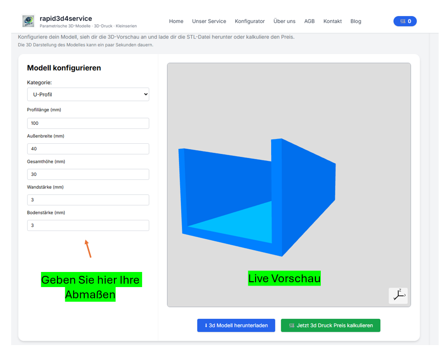
Nächster Schritt: Vorlage wählen & CAD-frei konfigurieren
Once you have the dimensions, you're practically done: choose the right template from the categories, trage die Werte ein, prüfe die Vorschau und generiere deine STL. This is exactly what BuildYour3D is there for: Enter dimensions instead of learning CAD.
Also searched for:
Measure spare part Caliper, measure hole distance center center, tolerance 3D pressure, Fit 3D print screw, custom adapter, print bracket without CAD, STL without CAD.
FAQ
Is a ruler sufficient or do I need a caliper gauge?
A ruler is sufficient for rough prototypes. If it is fit (drill holes, plug-in fits), a caliper gauge is highly recommended - most problems are caused by inaccurate measurements.
How do I find the right model for my replacement part?
Start with the categories. Select the template that comes closest to the part (e.g. holder/adapter/spacer). Then adjust the dimensions accordingly.
My part has unusual shapes - what then?
Then send us a photo + 2-3 core dimensions via Contact. We can often add a suitable parametric template or recommend the right base.