Gears ·
How to Measure a Gear: Module, Outside Diameter, Pitch Diameter and Number of Teeth
Learn how to measure a broken gear, calculate the module, determine the pitch diameter and configure a replacement gear online.
How to measure a gear step by step
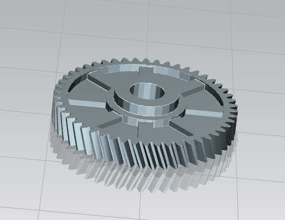
If a gear is broken or worn, you can often recreate it with a few key measurements. The most important values are the number of teeth z, the outside diameter da, the module m and the resulting pitch diameter d.
1. Count the number of teeth z
Count all teeth around the gear once. Mark one tooth as the starting point to avoid counting it twice.
2. Measure the outside diameter da
For a removed gear, the easiest value to measure is usually the outside diameter across the tooth tips. This is called the outside diameter or addendum circle diameter da.
3. Calculate the module m
For a standard spur gear without profile shift, use:
m = da / (z + 2)
Example: outside diameter da = 52 mm, number of teeth z = 24. Therefore: m = 52 / 26 = 2 mm.
4. Calculate the pitch diameter d
The pitch diameter is not the same as the outside diameter. The pitch diameter is calculated as:
d = m · z
Example: d = 2 · 24 = 48 mm.
5. Configure the replacement gear
Enter the number of teeth, module, width, bore diameter and other dimensions in the gear configurator. You can then generate a custom STL model for 3D printing.
Important note
Do not confuse outside diameter with pitch diameter. If you divide the outside diameter directly by the number of teeth, the module will be incorrect.
Nächster Schritt