


Dust Extraction ·
Custom Dust Extraction Flange Adapter: How to Connect a Machine, Pipe and Hose
Your machine enclosure has a large round opening, but your dust extraction hose uses a smaller diameter? This practical guide explains how to measure and configure a custom flange adapter, size the hose connection, and avoid common mistakes involving the transition cone, mounting holes, sealing and 3D printing.
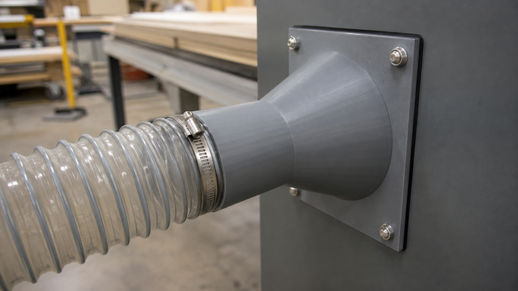
Many dust collection problems begin at the final connection rather than at the extractor itself. A machine, enclosure or ventilation opening has no suitable spigot, while the available hose uses a different diameter. Standard fittings often fail in exactly these situations, especially on older machinery, custom-built enclosures and non-standard mounting surfaces.
A custom dust extraction flange adapter solves this specific interface problem. It connects a large circular opening in a rectangular mounting plate to a smaller round pipe or hose connection through a tapered transition. One technical distinction matters: the plate is rectangular, but both airflow openings are circular. This is therefore not a true rectangular-to-round duct transition.
When is a custom flange adapter useful?
Searches such as dust collection hose adapter, dust extraction machine connector, hose flange adapter and 3D printed duct adapter usually reflect a practical need: connecting an existing hose to a machine or enclosure when no off-the-shelf fitting matches both sides.
- Workshop machinery: connect extraction ducting to a router, saw, sanding enclosure or CNC cabinet.
- Cabinets and housings: route air from technical cabinets, electronics enclosures or custom filter boxes.
- Repairs and prototypes: replace an unavailable plastic flange or test a new outlet diameter.
- Custom ventilation: transition from a large circular enclosure opening to a smaller round duct.
Configure your custom extraction adapter
Set the mounting plate, inlet, outlet, transition and bolt-hole dimensions without designing the part from scratch in CAD.
Before configuring: distinguish inside and outside diameter
The most common measurement error is confusing inside diameter with outside diameter. If a flexible hose must slide over the spigot, the hose's measured inside diameter is the starting point for the connection's outside diameter. If the spigot must slide inside a rigid pipe, the pipe's inside diameter and the required fit become decisive. Manufacturing variation, material flexibility and whether the connection must remain removable determine the clearance you need.
The connection's inside diameter defines the clear airflow area. Its approximate wall thickness follows from the two diameter settings:
Wall thickness = (outside diameter − inside diameter) / 2
Check this value in the preview. A very thin wall can deform when a hose clamp is tightened, while an unnecessarily thick wall reduces the open flow area.
Every configurator parameter explained
Base plate width and height
These dimensions define the outside size of the rectangular mounting plate. Measure more than the available flat area: allow room for screw heads, washers, tool access and sufficient material between each mounting hole, the plate edge and the large central opening. If the adapter replaces an existing component, measure its contact surface directly.
Base plate thickness
Plate thickness affects stiffness, flatness and load distribution beneath the fasteners. A thicker plate is not automatically airtight. A flat mating surface, a suitable gasket or sealing tape and even screw tightening are equally important.
Large inside diameter
This is the clear diameter of the large opening on the flange side. Measure the machine or enclosure opening in at least two directions. The adapter should not unintentionally obstruct the airflow path, but enough material must remain around the opening for the plate and its mounting holes.
Connection outside and inside diameter
The outside diameter determines which hose can slide over the spigot or which mating part can receive it. The inside diameter is the actual unobstructed flow diameter. Do not rely solely on a hose's nominal size: wall construction, reinforcement and manufacturer tolerances can produce measurable differences. A caliper gives a more dependable starting point.
Transition cone height
A short cone saves space but creates a more abrupt geometry change. A longer transition changes the cross-section more gradually, although it needs more installation depth. Its effect on performance depends on the entire system—including the fan, filter, hose length, ducting and other restrictions—and should be tested where airflow is critical.
Mounting-hole diameter
Select a hole diameter that suits the fasteners and the required installation clearance. Before manufacturing, inspect the preview to confirm that all four corner holes lie fully on the mating surface, retain enough edge distance and do not intersect the large central opening. For an existing machine, verify the actual mounting pattern as well as the hole diameter.
How to measure the adapter in seven steps
- Switch off the machine and secure it against accidental start-up.
- Measure the width and height of the usable flat mounting area.
- Measure the large circular opening in at least two perpendicular directions.
- Record the fastener size, required hole clearance and usable edge areas.
- Measure the hose inside diameter or the mating pipe's actual inside diameter.
- Check the available depth for the cone, straight spigot, clamp and hose bend radius.
- Inspect the generated 3D preview for thin walls and possible collisions.
Why the clear airflow area matters
For a circular connection, cross-sectional area is calculated as A = π × d² / 4. Even a moderate diameter reduction produces a substantial reduction in area. At an unchanged volume flow, air velocity would follow v = Q / A. In a real extraction system, however, volume flow does not remain automatically constant: the adapter, hose, filter, pipe network and other restrictions affect the operating point. Avoid making the clear outlet smaller than necessary.
For example, a clear diameter of 100 mm provides approximately 7,854 mm² of area, whereas 80 mm provides only about 5,027 mm². Reducing the diameter from 100 to 80 mm therefore reduces the area by roughly 36 percent. This is not a prediction of extractor performance, but it demonstrates why the inside diameter deserves deliberate attention.
Installation: sealed, stress-free and serviceable
- Clean the flange and mating surface and inspect both for uneven areas.
- Use a suitable closed-cell gasket or sealing tape where required.
- Tighten the four screws gradually in a cross pattern to limit plate distortion.
- Push the hose far enough onto the cylindrical section of the spigot.
- Position the hose clamp on the straight section, not on the taper.
- After the first run, inspect the connection for leakage, vibration, movement and deformation.
Material and 3D printing considerations
PLA is often suitable for dimensional checks and prototypes in dry, moderately warm environments. Depending on the exact grade and print setup, PETG may provide greater toughness and temperature resistance, while ASA may be relevant where heat or UV exposure is higher. Actual suitability depends on operating temperature, chemicals, mechanical loads and print settings.
For a functional print, focus on a flat flange face, sufficient perimeters, strong layer adhesion around the spigot and a clean internal surface. FDM parts are not automatically airtight. If leakage matters, test the completed part and add an application-compatible gasket or surface treatment where necessary.
Common mistakes to avoid
- Using nominal size as the real measurement: a hose labelled 4 inches or 100 mm may not measure exactly that size internally.
- Treating outside diameter as clear bore: this makes wall thickness uncertain or reduces the planned airflow opening.
- Leaving no room for the clamp: the clamp belongs on the straight spigot, not on the transition cone.
- Estimating the mounting holes: a small positional error can prevent installation even when the diameters are correct.
- Mounting the flange without a seal: a printed face does not reliably compensate for an uneven panel.
- Treating the adapter as the complete system design: a correctly sized fitting cannot compensate for an undersized extractor, blocked filter or unsuitable duct network.
Practical example: connecting a CNC enclosure to a flexible hose
Suppose a CNC enclosure has a large circular outlet in a flat rear panel, but the extraction hose is smaller. First measure the panel opening and the flat area around it. Then measure the actual inside diameter of the hose, check how far it can slide over a spigot and reserve enough straight length for the clamp. The cone height is chosen last, based on the remaining clearance behind the machine and the hose's minimum bend radius. This sequence prevents a common outcome: a dimensionally correct adapter that cannot be mounted because the hose or clamp hits a wall.
Frequently asked questions
Is this a rectangular-to-round duct adapter?
No. The mounting plate is rectangular, but its central opening is circular. Air passes from a large round opening through a cone to a smaller round connection.
Which dimension do I need for a flexible hose?
If the hose slides over the spigot, measure its real inside diameter. Also account for flexibility, reinforcement, manufacturing tolerance and the amount of clamping required.
How long should the transition cone be?
Use a length that fits the available space while avoiding an unnecessarily abrupt transition. A longer cone changes the cross-section more gradually, but its effect must be evaluated as part of the complete extraction system.
Will reducing the diameter improve suction?
Not automatically. A smaller area may increase local air velocity under some conditions, but it also adds restriction and can reduce total airflow. The actual result depends on the fan curve, filter, ducting, hose length and every other pressure loss in the system.
Can this adapter be used for hot exhaust or hazardous dust?
Not without professional assessment of the material, temperature, fire safety, electrostatic behaviour and applicable system requirements. It is not a certified pressure, breathing-air or explosion-protection component. Flammable or explosive dust, solvent vapours, hot exhaust and pressure systems require approved equipment and competent engineering.
Can I order the configured part or obtain a 3D model?
Use the product configurator to enter your dimensions, inspect the preview and review the currently offered file and manufacturing options.
Use your measurements—not the nearest standard size
Transfer the measured plate, opening and hose dimensions into the configurator and verify the complete geometry in the 3D preview.
Safety note: Workshop dust extraction also requires suitable hoses, appropriate electrostatic grounding or bonding, adequate filtration and compliance with the machine and extractor manufacturers' instructions. This guide does not replace professional extraction-system design.