


Adapter Plates ·
Custom Adapter Plate: Round or Rectangular with Two Bolt Patterns
Round or rectangular, both versions use the same mounting logic: a center opening, an inner bolt circle A and an outer rectangular four-hole pattern B. This guide explains every measurement and shows how to connect motors, pumps, blowers and machine frames with incompatible mounting patterns.
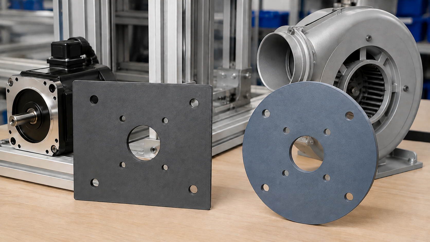
A motor suits the machine, but its mounting holes are in the wrong positions. A blower has a round flange, while the existing bracket uses a rectangular four-hole pattern. Or a replacement device must fit an established frame without drilling new holes into the structure. A custom adapter plate solves this exact interface problem by placing two incompatible mounting patterns on one component.
The configurator creates either a rectangular mounting plate or a round flange plate. Both outer shapes use the same functional geometry: an optional center opening, an adjustable inner bolt circle A and an outer rectangular four-hole pattern B. Changing the outline does not automatically change the hole layout. A round plate can still carry rectangular pattern B as long as all four holes remain inside the circular outline.
A common arrangement uses bolt circle A for the new motor, pump or blower and pattern B for the existing frame—or the other way around. This makes the plate useful for prototypes, retrofits, fixtures, equipment repairs and custom machine installations.
What do people actually want from a custom adapter plate?
Searches such as custom mounting plate with bolt pattern, motor adapter plate, round flange plate custom size and bolt circle adapter plate normally reflect one practical goal: attach an existing device to a mounting surface whose hole pattern does not match. Accurate datums matter more than adding as many holes as possible.
- Motor to machine frame: four outer frame holes plus an inner bolt circle for the motor flange.
- Fan or blower mounting: round plate with a clear center opening and two different attachment patterns.
- Pump or dosing drive: translate an existing base pattern to the bolt pattern of a replacement unit.
- Retrofit and repair: install new equipment without modifying the original structure.
- Fixture building: position a sensor, bearing support or test component on a defined mounting surface.
Configure an adapter plate without CAD
Set the outer shape, plate dimensions, center opening, bolt circle A and four-hole pattern B to match the two components.
Round or rectangular: which outer shape should you choose?
| Feature | Rectangular version | Round version |
|---|---|---|
| Outside size | Width and height set separately | Plate width becomes outside diameter |
| Typical mating surface | Machine frame, enclosure, aluminum extrusion | Blower, fan, pump or circular flange |
| Center opening | Optional and circular | Optional and circular |
| Bolt circle A | Equally spaced inner holes | Equally spaced inner holes |
| Pattern B | Four outer holes in a rectangle | Also available if it fits inside the circle |
Rectangular adapter plate
The rectangular outline suits machine frames, aluminum-extrusion structures, enclosure walls and devices with rectangular bases. Width and height are independent, making the plate easy to align with edges and leaving a predictable area for rectangular pattern B.
Application example: A servo motor must attach to an aluminum-extrusion frame. The four outer holes connect the plate to the frame, while the inner bolt circle matches the motor face and the center opening clears the shaft or locating boss.
Round adapter plate
The round outline suits fans, blowers, pumps, duct flanges and other rotationally symmetric components. For this version, “plate width / diameter” defines the outside diameter; the separate plate-height setting does not define the circular outline.
Application example: A blower with a round inlet must attach to an existing bracket with four mounting points arranged in a rectangle. The center opening preserves airflow, bolt circle A fastens the blower, and pattern B connects the plate to the existing bracket.
Every configurator parameter explained
Outer shape: rect or round
“rect” creates a rectangular plate and “round” creates a circular one. Choose the outline that matches the available contact surface and leaves enough material around every opening. A circular plate can save space on a symmetric assembly; a rectangle normally offers more room for offset mounting points.
Plate width / diameter
For the rectangular version, this is the total width. For the round version, it is the outside diameter. Measure the usable mating surface and allow room for bolt heads, washers, tools and suitable edge distances.
Plate height
This setting defines the outside height of the rectangular version. Check not only the nominal mounting surface but also nearby cables, enclosure ribs, profile slots and covers.
Material thickness
Thickness affects stiffness, flatness, fastener bearing and the axial distance between the two assemblies. A thicker printed plate is not automatically safe for higher loads: material, print orientation, bolt preload, leverage, temperature and cyclic loading still matter. On rotating equipment, include the added plate thickness when checking shaft engagement, coupling position and belt alignment.
Center opening
The center opening is a circular through-hole for a shaft, locating boss, cable bundle, airflow path or pipe. A value of 0 disables the opening and leaves the plate closed. For a locating feature, measure both diameter and required clearance rather than copying only the nominal size.
Pattern A: adjustable bolt circle
Pattern A distributes a selected number of holes evenly around a pitch circle. You control hole diameter, bolt circle diameter, hole count and rotation angle. The bolt circle diameter—often abbreviated BCD or PCD—is the diameter of the imaginary circle passing through the centers of all holes, not the outside distance across them.
Rotation angle A
The rotation angle turns the entire circular pattern around the plate center. This matters when one hole must sit at the top or when the holes must avoid ribs, edges or pattern B. For equal spacing, the angular interval is 360° / number of holes.
Pattern B: rectangular four-hole pattern
Pattern B always uses four holes. “Hole spacing B X” is the total horizontal center-to-center distance between the left and right hole columns. “Hole spacing B Y” is the total vertical center-to-center distance between the upper and lower rows. These values are hole-center distances, not edge-to-edge dimensions.
How to measure a bolt circle correctly
With an even number of holes, the BCD can often be measured between the centers of two opposite holes. If the hole centers are difficult to access, the bore diameter may need to be added or subtracted depending on where the caliper contacts. For an odd hole count or an unknown pattern, use the manufacturer's drawing, a drilling template or coordinates derived from several measured centers.
A hole position on circle A can be represented by x = r × cos(α) and y = r × sin(α), where r = BCD / 2. The rotation angle shifts every hole angle together. You do not need this calculation to use the configurator, but it is useful when validating a measured pattern.
How to measure rectangular pattern B
- Establish clear horizontal and vertical datum directions.
- Measure from the center of the left hole to the center of the right hole: B X.
- Measure from the center of the upper hole to the center of the lower hole: B Y.
- Measure the hole diameter separately.
- Confirm that the real pattern is centered on the component.
If the real four-hole pattern is offset from the center, a symmetric plate may not reproduce it. Do not compensate by making the holes excessively large; use an appropriate custom design instead.
Check that the two patterns fit together
- Edge distance: enough material must remain between each hole edge and the plate outline.
- Center opening: it must not cut into the mounting holes, washers or bearing areas.
- Patterns A and B: their holes, bolt heads and nuts must not collide.
- Tool access: allow room for a hex key, socket or spanner.
- Mating parts: every fastener must engage real threaded material or its intended nut.
- Location: clearance bolts alone do not provide precision shaft or bearing alignment.
Choosing the mounting-hole diameter
A clearance hole is normally larger than the bolt's nominal diameter. The required allowance depends on bolt size, manufacturing process, alignment needs and the relevant standard. Printed holes can finish smaller than modeled. For a critical fit, print a small test coupon or plan to drill or ream the holes after printing.
High sustained loads should not be transferred into plastic only through small bolt-head areas. Washers, bushings, metal inserts or a different manufacturing method may be needed. The correct approach depends on the actual load case.
3D printing orientation and material
Printing a flat plate flat on the build surface normally produces clean XY hole geometry and a straightforward base shape. Use adequate perimeters, suitable infill and reliable layer adhesion. Do not tighten fasteners until the plastic creeps or the plate visibly bows.
- PLA: useful for dimensional prototypes, fixtures and lightly loaded parts at stable room temperature.
- PETG: may suit tougher workshop parts depending on print quality and operating temperature.
- ASA: may offer advantages under UV or moderately elevated temperatures when processed correctly.
A material name alone does not guarantee strength. Print orientation, layer bonding, stress concentrations around holes, temperature and continuous loading all influence performance.
Common adapter-plate mistakes
- Confusing BCD with hole spacing: BCD is the diameter through the hole centers.
- Measuring B X and B Y between hole edges: the configurator expects center-to-center spacing.
- Ignoring rotation angle: the hole spacing is right, but the entire circle is rotated.
- Making the center opening too large: holes or washer contact areas are cut away.
- Forgetting bolt-head access: the holes align, but assembly is impossible.
- Ignoring the axial offset: a shaft, coupling or belt no longer reaches its intended position.
- Assuming printed plastic is automatically industrial-grade: safety and fatigue loads require engineering verification.
Important distinction: this is not a vehicle wheel adapter
Search engines often associate “bolt pattern adapter” with wheel spacers and automotive conversions. This configurable model is not intended for that purpose and has no vehicle approval, strength certification or roadworthiness documentation. Never use it for wheels, brakes, steering or other safety-critical vehicle components.
Frequently asked questions
Can bolt circle A and pattern B be used at the same time?
Yes. They can represent the two different mating components. Check the preview for collisions between holes, fastener heads, center opening and plate edge.
What happens when the center opening is set to 0?
The central opening is disabled and the middle of the plate remains solid.
What does bolt circle diameter mean?
It is the diameter of the imaginary circle on which the centers of all pattern-A holes are positioned.
Can a round plate use rectangular pattern B?
Yes, provided all four holes and their fastener-bearing areas remain fully inside the circular outline.
Can the adapter plate be used for motors and pumps?
It can serve as a geometric interface for prototypes and appropriately verified installations. Load capacity, concentricity, vibration, temperature, torque and fastener retention must be assessed separately.
Can it be used as a pressure flange?
Not without professional design, material verification, a sealing concept and testing. The model is not a certified pressure flange.
Connect two existing bolt patterns cleanly
Measure the outer shape, center opening, bolt circle and four-hole spacing directly from the mating parts, then verify the combined geometry in the 3D preview.
Safety note: Do not use this part for vehicle wheels, braking or steering, lifting equipment, personnel protection, pressure vessels or other safety-critical joints without documented engineering verification. Follow manufacturer requirements for alignment, guarding and fastener retention on motors and rotating machinery.