


Lighting Installation ·
New Ceiling Light Holes Do Not Line Up? Use a Custom Mounting Adapter Plate
Your old ceiling holes are 70 mm apart, but the new light fixture needs 90 mm. A configurable ceiling lamp mounting adapter bridges both hole spacings, keeps the cable passage centred and adds slots for final alignment.
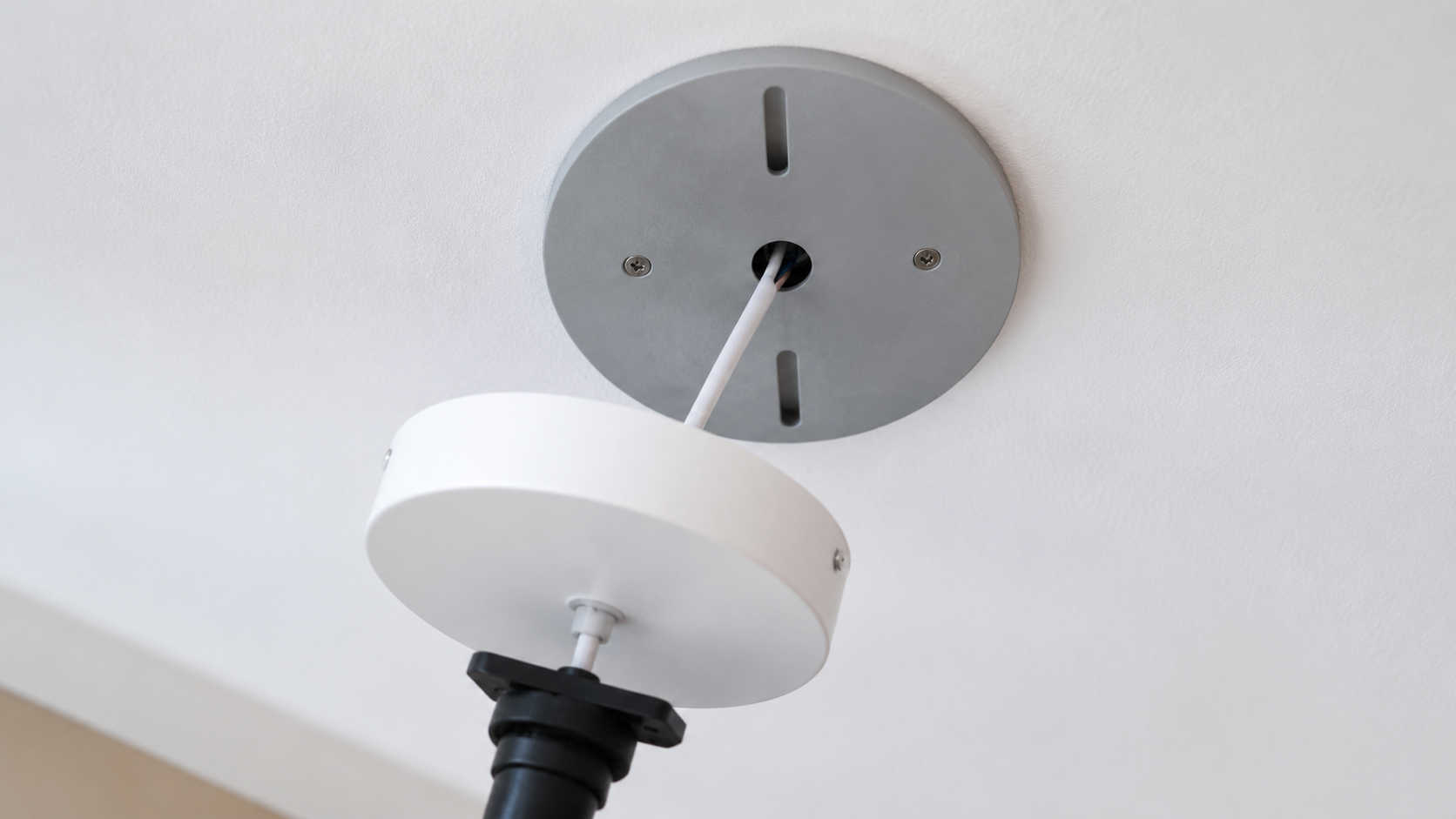
You have unpacked the new ceiling light, only to discover that its mounting bracket does not match the existing holes. This is the exact problem behind searches such as ‘ceiling light mounting holes do not line up’, ‘ceiling light adapter plate’, ‘light fixture mounting bracket does not fit’ and ‘reuse old ceiling holes’. The problem sounds simple, but drilling blindly beside a ceiling cable outlet can damage concealed wiring, while moving the canopy off-centre often looks untidy.
The Parametric Ceiling Lamp Mount Adapter provides a clean mechanical interface between two different fixing patterns. Instead of filing a generic plate until it almost fits, you enter the existing spacing and the spacing required by the new fixture. The generated model combines a central cable opening, two round holes and two opposing adjustment slots on one circular plate.
Configure an adapter plate for your ceiling
Set the outer diameter, old and new hole spacing, cable opening, plate thickness and slot length, then inspect the generated 3D preview.
When is a ceiling light adapter plate useful?
The most common use case is a light-fixture replacement. The previous lamp was secured through two sound ceiling anchors, but the new bracket uses another centre-to-centre distance. A correctly designed adapter plate can connect those patterns while keeping the cable outlet accessible.
- A new LED ceiling light has a different fixing distance from the old lamp.
- Existing holes lie close to the cable outlet and unnecessary drilling should be avoided.
- The canopy needs to cover old holes or an untidy cable opening.
- The fixture needs a few millimetres of adjustment before final tightening.
- A circular adapter must remain hidden inside the lamp canopy.
The plate cannot make loose plugs, cracked plaster or an unsuitable ceiling structure safe. It does not replace approved anchors, the fixture manufacturer's instructions or a proper assessment of the substrate and load.
How to measure the hole spacing correctly
The most frequent configuration error is measuring between the edges of two different holes. Hole spacing is normally specified centre to centre. If the existing screws are still installed, measure between their centres. For two holes of equal diameter, measuring from the left edge of one hole to the left edge of the other also gives the centre distance.
Record two separate dimensions. Old Hole Spacing describes the existing ceiling fixing points. New Hole Spacing comes from the mounting bracket or canopy of the new lamp. Measure the physical component whenever possible rather than relying on a drawing with unclear reference points.
What each parameter controls
Outer Diameter
The outer diameter determines how much ceiling area the plate covers. It must be large enough to contain both fixing patterns with adequate material around every opening, yet small enough to fit fully inside the canopy. Check for drivers, terminals and other internal canopy components as well.
Cable Opening
The central opening must allow the intended insulated cable and any required protective fitting to pass without pinching. An appropriate grommet, edge protection or strain relief may be necessary. Set the value to 0 only for a genuinely closed plate where no cable passes through it.
Plate Thickness
A thicker plate is not automatically a higher-rated mounting solution. Thickness affects stiffness, available space and the required screw length. Fasteners must still achieve the necessary engagement in the intended anchor without becoming long enough to endanger concealed services.
Old and New Hole Spacing
These dimensions create the interface between ceiling and fixture. Inspect the preview for collisions between the two patterns, the cable opening and the outer edge. Also confirm that every screw remains accessible during installation.
Hole Diameter and Slot Length
The hole diameter should suit the selected screws and washers. A small amount of assembly clearance is useful, but oversized holes are not a substitute for accurate measurement. Longer slots provide more adjustment, while also reducing the material remaining at each end. The screw head or washer must safely overlap the complete slot width.
Worked example: 70 mm existing spacing to 90 mm new spacing
Suppose the existing ceiling fixings are 70 mm apart and a new round LED fixture requires 90 mm. First measure the inside of the canopy because it limits the plate diameter. Then enter the cable-opening diameter, both centre distances, the intended screw clearance and only as much slot adjustment as the installation needs.
Before ordering or downloading the STL, rotate the preview and check that sufficient material remains around every opening. During installation, one fixing pattern connects the adapter to suitable existing ceiling anchors and the other accepts the new lamp bracket. This is an example, not a universal load approval: the substrate, anchors, screws, print material and fixture weight must work safely as one system.
Pre-order measurement checklist
- Measure the inside of the canopy and determine the maximum adapter diameter.
- Measure both old and new hole spacings centre to centre.
- Check the cable outlet, cable diameter, bend radius and required strain relief.
- Match the screw diameter, hole clearance, head size and washers.
- Confirm adequate edge distance around holes and slot ends.
- Assess the ceiling material, existing anchors, fixture mass and leverage.
- Check for collisions with the driver, connectors and canopy.
- Review the generated 3D model from several angles.
Installation safety: electricity and overhead loads
Mains-voltage electrical work must be handled by a suitably qualified person and in accordance with local regulations. Isolate the correct circuit, prevent accidental re-energisation and verify that the conductors are dead with appropriate test equipment. Switching off the wall switch is not sufficient. Unknown legacy wiring or a missing protective conductor requires professional assessment.
This adapter is not an electrical enclosure, junction box, fire barrier or certified ceiling anchor. Terminals and drivers must remain inside an enclosure or canopy approved for that purpose. Never pinch the cable or route its insulation across an unprotected edge.
For a 3D-printed part, material temperature resistance, creep, print orientation and flammability also matter. Keep the adapter away from hot lamp components and drivers. Heavy chandeliers, dynamically loaded fittings and ceiling fans require a properly engineered and approved structural mounting solution.
Common mistakes that cause a poor fit
- Measuring edge to edge instead of centre to centre.
- Choosing a plate that does not fit inside the canopy.
- Making the cable opening so small that the cable is pinched.
- Using excessive slot length to compensate for an incorrect spacing value.
- Ignoring screw-head and washer clearance inside the canopy.
- Reusing loose or damaged ceiling anchors without checking them.
- Assuming more printed thickness guarantees more load capacity.
Frequently asked questions
Can the adapter prevent any new drilling?
Only when the existing fixing points are sound, correctly positioned and suitable for the complete load. The plate translates a hole pattern; it cannot repair weak anchors or create structural support in the ceiling.
How large should the cable opening be?
Large enough for the intended cable and protective fitting to pass without damage, but no larger than necessary. Allow for bend radius, edge protection and strain relief. A qualified electrician should decide if the cable arrangement is uncertain.
What are the elongated slots for?
They provide limited fine adjustment and help align the fixture before tightening. They are not intended to correct a fundamentally wrong hole spacing or a severely offset installation.
Will the plate cover old holes?
It can, provided the selected outer diameter covers the marks and still fits under the canopy. Unused holes should nevertheless be inspected and repaired appropriately.
Is it suitable for every ceiling light?
No. Suitability depends on fixture weight and centre of gravity, ceiling construction, anchors, fasteners, temperature, canopy geometry and the manufacturer's installation requirements.
Can I download an STL after configuring it?
Yes. The product page generates the model from your dimensions and provides an STL workflow as well as an option to continue towards a printed part. Always verify dimensions, tolerances, orientation and material before use.
Bridge the old and new mounting patterns
Enter your measured dimensions, adjust the cable opening and slots, and verify the result in the interactive 3D preview.